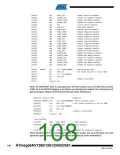
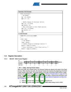
Assembly Code Example
Move_interrupts:
; Get MCUCR
in r16, MCUCR
mov r17, r16
; Enable change of Interrupt Vectors
ori r16, (1<<IVCE)
out MCUCR, r16
; Move interrupts to Boot Flash section
ori r16, (1<<IVSEL)
out MCUCR, r17
ret
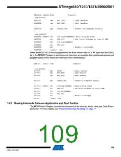
C Code Example
void Move_interrupts(void)
{
uchar temp;
/* Get MCUCR*/
temp = MCUCR;
/* Enable change of Interrupt Vectors */
MCUCR = temp|(1<<IVCE);
/* Move interrupts to Boot Flash section */
MCUCR = temp|(1<<IVSEL);
}
14.4 Register Description
14.4.1
MCUCR – MCU Control Register
Bit
7
6
–
5
–
4
3
–
2
–
1
IVSEL
R/W
0
0
IVCE
R/W
0
0x35 (0x55)
Read/Write
Initial Value
JTD
R/W
0
PUD
R/W
0
MCUCR
R
0
R
0
R
0
R
0
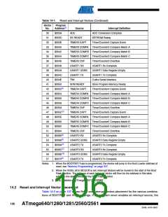
• Bit 1 – IVSEL: Interrupt Vector Select
When the IVSEL bit is cleared (zero), the Interrupt Vectors are placed at the start of the Flash
memory. When this bit is set (one), the Interrupt Vectors are moved to the beginning of the Boot
Loader section of the Flash. The actual address of the start of the Boot Flash Section is deter-
mined by the BOOTSZ Fuses. Refer to the section “Memory Programming” on page 337 for
details. To avoid unintentional changes of Interrupt Vector tables, a special write procedure must
be followed to change the IVSEL bit (see “Moving Interrupts Between Application and Boot Sec-
tion” on page 109):
1. Write the Interrupt Vector Change Enable (IVCE) bit to one.
2. Within four cycles, write the desired value to IVSEL while writing a zero to IVCE.
110
ATmega640/1280/1281/2560/2561
2549L–AVR–08/07

 ATMEL [ ATMEL ]