ATmega640/1280/1281/2560/2561
14. Interrupts
This section describes the specifics of the interrupt handling as performed in
ATmega640/1280/1281/2560/2561. For a general explanation of the AVR interrupt handling,
refer to “Reset and Interrupt Handling” on page 17.
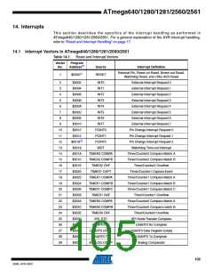
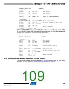
14.1 Interrupt Vectors in ATmega640/1280/1281/2560/2561
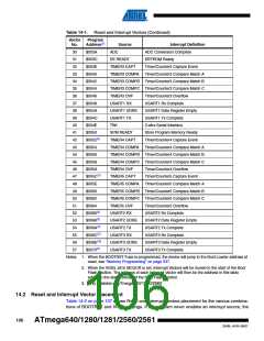
Table 14-1. Reset and Interrupt Vectors
Vector
No.
Program
Address(2)
Source
Interrupt Definition
External Pin, Power-on Reset, Brown-out Reset,
1
$0000(1)
RESET
Watchdog Reset, and JTAG AVR Reset
2
$0002
$0004
$0006
$0008
$000A
$000C
$000E
$0010
$0012
$0014
$0016(3)
$0018
$001A
$001C
$001E
$0020
$0022
$0024
$0026
$0028
$002A
$002C
$002E
$0030
$0032
$0034
$0036
$0038
INT0
INT1
External Interrupt Request 0
External Interrupt Request 1
External Interrupt Request 2
External Interrupt Request 3
External Interrupt Request 4
External Interrupt Request 5
External Interrupt Request 6
External Interrupt Request 7
Pin Change Interrupt Request 0
Pin Change Interrupt Request 1
Pin Change Interrupt Request 2
Watchdog Time-out Interrupt
Timer/Counter2 Compare Match A
Timer/Counter2 Compare Match B
Timer/Counter2 Overflow
3
4
INT2
5
INT3
6
INT4
7
INT5
8
INT6
9
INT7
10
11
12
13
14
15
16
17
18
19
20
21
22
23
24
25
26
27
28
29
PCINT0
PCINT1
PCINT2
WDT
TIMER2 COMPA
TIMER2 COMPB
TIMER2 OVF
TIMER1 CAPT
TIMER1 COMPA
TIMER1 COMPB
TIMER1 COMPC
TIMER1 OVF
TIMER0 COMPA
TIMER0 COMPB
TIMER0 OVF
SPI, STC
Timer/Counter1 Capture Event
Timer/Counter1 Compare Match A
Timer/Counter1 Compare Match B
Timer/Counter1 Compare Match C
Timer/Counter1 Overflow
Timer/Counter0 Compare Match A
Timer/Counter0 Compare match B
Timer/Counter0 Overflow
SPI Serial Transfer Complete
USART0 Rx Complete
USART0 RX
USART0 UDRE
USART0 TX
ANALOG COMP
USART0 Data Register Empty
USART0 Tx Complete
Analog Comparator
105
2549L–AVR–08/07

 ATMEL [ ATMEL ]