22. Digital to Analog Converter - DAC
22.1 Features
• 10 bits resolution
• 8 bits linearity
• +/- 0.5 LSB accuracy between 150mV and AVcc-150mV
• Vout = DAC*Vref/1023
• The DAC could be connected to the negative inputs of the analog comparators and/or to a
dedicated output driver.
• Output impedance around 100 Ohm.
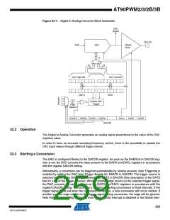
The AT90PWM2/2B/3/3B features a 10-bit Digital to Analog Converter. This DAC can be used
for the analog comparators and/or can be output on the D2A pin of the microcontroller via a ded-
icated driver.
This allows to drive (worst case) a 1nF capacitance in parallel with a resistor higher than 33K
load with a time constant around 1us. Response time and power consumption are improved by
reducing the load (reducing the capacitor value and increasing the load resistor value (The best
case is a high impedance)).
The DAC has a separate analog supply voltage pin, AVCC. AVCC must not differ more than
0.3V from VCC. See the paragraph “ADC Noise Canceler” on page 240 on how to connect this
pin.
The reference voltage is the same as the one used for the ADC, See “ADC Multiplexer Register
– ADMUX” on page 246.. These nominally 2.56V Vref or AVCC are provided On-chip. The volt-
age reference may be externally decoupled at the AREF pin by a capacitor for better noise
performance.
258
AT90PWM2/3/2B/3B
4317J–AVR–08/10

 ATMEL [ ATMEL ]