AT90PWM2/3/2B/3B
16.26.4 PSC2 Interrupt Mask Register – PIM2
Bit
7
-
6
-
5
PSEIE2
R/W
0
4
PEVE2B
R/W
0
3
PEVE2A
R/W
0
2
-
1
-
0
PEOPE2
R/W
0
PIM2
Read/Write
Initial Value
R
0
R
0
R
0
R
0
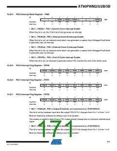
• Bit 5 – PSEIEn : PSC n Synchro Error Interrupt Enable
When this bit is set, the PSEIn bit (if set) generate an interrupt.
• Bit 4 – PEVEnB : PSC n External Event B Interrupt Enable
When this bit is set, an external event which can generates a capture from Retrigger/Fault block
B generates also an interrupt.
• Bit 3 – PEVEnA : PSC n External Event A Interrupt Enable
When this bit is set, an external event which can generates a capture from Retrigger/Fault block
A generates also an interrupt.
• Bit 0 – PEOPEn : PSC n End Of Cycle Interrupt Enable
When this bit is set, an interrupt is generated when PSC reaches the end of the whole cycle.
16.26.5 PSC0 Interrupt Flag Register – PIFR0
Bit
7
6
5
PSEI0
R/W
0
4
PEV0B
R/W
0
3
PEV0A
R/W
0
2
PRN01
R
1
PRN00
R
0
PEOP2
R/W
0
POAC0B
POAC0A
PIFR0
PIFR1
PIFR2
Read/Write
Initial Value
R
0
R
0
0
0
16.26.6 PSC1 Interrupt Flag Register – PIFR1
Bit
7
6
5
PSEI1
R/W
0
4
PEV1B
R/W
0
3
PEV1A
R/W
0
2
PRN11
R
1
PRN10
R
0
PEOP1
R/W
0
POAC1B
POAC1A
Read/Write
Initial Value
R
0
R
0
0
0
16.26.7 PSC2 Interrupt Flag Register – PIFR2
Bit
7
6
5
PSEI2
R/W
0
4
PEV2B
R/W
0
3
PEV2A
R/W
0
2
PRN21
R
1
PRN20
R
0
PEOP2
R/W
0
POAC2B
POAC2A
Read/Write
Initial Value
R
0
R
0
0
0
• Bit 7 – POACnB : PSC n Output B Activity (not implemented on AT90PWM2/3)
This bit is set by hardware each time the output PSCOUTn1 changes from 0 to 1 or from 1 to 0.
Must be cleared by software by writing a one to its location.
This feature is useful to detect that a PSC output doesn’t change due to a freezen external input
signal.
• Bit 6 – POACnA : PSC n Output A Activity (not implemented on AT90PWM2/3)
This bit is set by hardware each time the output PSCOUTn0 changes from 0 to 1 or from 1 to 0.
Must be cleared by software by writing a one to its location.
171
4317J–AVR–08/10

 ATMEL [ ATMEL ]