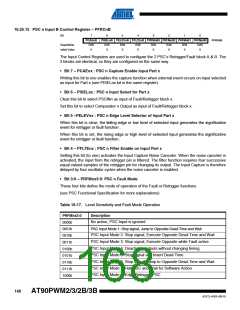
16.25.15 PSC n Input B Control Register – PFRCnB
Bit
7
PCAEnB
R/W
6
5
4
3
2
1
0
PFRCnB
PISELnB PELEVnB PFLTEnB PRFMnB3 PRFMnB2 PRFMnB1 PRFMnB0
Read/Write
Initial Value
R/W
0
R/W
0
R/W
0
R/W
0
R/W
0
R/W
0
R/W
0
0
The Input Control Registers are used to configure the 2 PSC’s Retrigger/Fault block A & B. The
2 blocks are identical, so they are configured on the same way.
• Bit 7 – PCAEnx : PSC n Capture Enable Input Part x
Writing this bit to one enables the capture function when external event occurs on input selected
as input for Part x (see PISELnx bit in the same register).
• Bit 6 – PISELnx : PSC n Input Select for Part x
Clear this bit to select PSCINn as input of Fault/Retrigger block x.
Set this bit to select Comparator n Output as input of Fault/Retrigger block x.
• Bit 5 –PELEVnx : PSC n Edge Level Selector of Input Part x
When this bit is clear, the falling edge or low level of selected input generates the significative
event for retrigger or fault function .
When this bit is set, the rising edge or high level of selected input generates the significative
event for retrigger or fault function.
• Bit 4 – PFLTEnx : PSC n Filter Enable on Input Part x
Setting this bit (to one) activates the Input Capture Noise Canceler. When the noise canceler is
activated, the input from the retrigger pin is filtered. The filter function requires four successive
equal valued samples of the retrigger pin for changing its output. The Input Capture is therefore
delayed by four oscillator cycles when the noise canceler is enabled.
• Bit 3:0 – PRFMnx3:0: PSC n Fault Mode
These four bits define the mode of operation of the Fault or Retrigger functions.
(see PSC Functional Specification for more explanations)
Table 16-17. Level Sensitivity and Fault Mode Operation
PRFMnx3:0
0000b
0001b
0010b
0011b
0100b
0101b
0110b
0111b
1000b
Description
No action, PSC Input is ignored
PSC Input Mode 1: Stop signal, Jump to Opposite Dead-Time and Wait
PSC Input Mode 2: Stop signal, Execute Opposite Dead-Time and Wait
PSC Input Mode 3: Stop signal, Execute Opposite while Fault active
PSC Input Mode 4: Deactivate outputs without changing timing.
PSC Input Mode 5: Stop signal and Insert Dead-Time
PSC Input Mode 6: Stop signal, Jump to Opposite Dead-Time and Wait.
PSC Input Mode 7: Halt PSC and Wait for Software Action
PSC Input Mode 8: Edge Retrigger PSC
168
AT90PWM2/3/2B/3B
4317J–AVR–08/10

 ATMEL [ ATMEL ]