RESET: A low state on the reset pin (RESET) will terminate the operation in progress and
reset the internal state machine to an idle state. The device will remain in the reset condition
as long as a low level is present on the RESET pin. Normal operation can resume once the
RESET pin is brought back to a high level.
The device incorporates an internal power-on reset circuit, so there are no restrictions on the
RESET pin during power-on sequences. If this pin and feature are not utilized it is recom-
mended that the RESET pin be driven high externally.
READY/BUSY: This open-drain output pin will be driven low when the device is busy in an
internally self-timed operation. This pin, which is normally in a high state (through a 1kΩ exter-
nal pull-up resistor), will be pulled low during programming operations, compare operations,
and during page-to-buffer transfers.
The busy status indicates that the Flash memory array and one of the buffers cannot be
accessed; read and write operations to the other buffer can still be performed.
Power-on/Reset
State
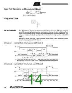
When power is first applied to the device, or when recovering from a reset condition, the
device will default to SPI Mode 3. In addition, the SO pin will be in a high-impedance state, and
a high-to-low transition on the CS pin will be required to start a valid instruction. The SPI mode
will be automatically selected on every falling edge of CS by sampling the inactive clock state.
After power is applied and VCC is at the minimum datasheet value, the system should wait
20 ms before an operational mode is started.
System
Considerations
DataFlash is controlled by the Serial Clock (SCK) and Chip Select (CS) pins. These signals
must rise and fall monotonically and be free from noise. Excessive noise or ringing on these
pins can be misinterpreted as multiple edges and cause improper operation of the device. The
PC board traces must be kept to a minimum distance or appropriately terminated. If neces-
sary, decoupling capacitors can be added on these pins to provide filtering against noise
glitches.
As system complexity continues to increase, voltage regulation is becoming more important. A
key element of any voltage regulation scheme is its current sourcing capability. Like all Flash
memories, the peak currents for DataFlash occur during the programming and erase opera-
tions. The peak current during programming or erase of a DataFlash is 70 mA to 80 mA. The
regulator needs to supply this peak current requirement. An under specified regulator can
cause current starvation. Besides increasing system noise, current starvation during program-
ming or erase can lead to improper operation and possible data corruption.
10
AT45DB011B
1984H–DFLSH–10/04

 ATMEL [ ATMEL ]