AT90USB82/162
Then, cleared by software to complete the reset operation and start using the FIFO.
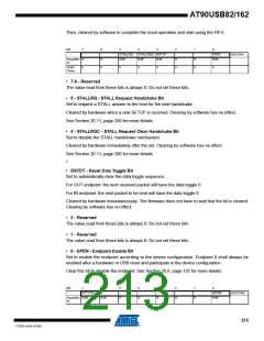
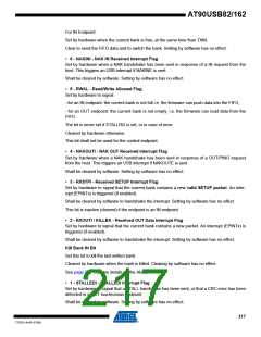
Bit
7
-
6
-
5
4
3
2
-
1
-
0
STALLRQ
R/W
STALLRQC RSTDT
EPEN
R/W
UECONX
Read/Wri
te
R
R
R/W
R/W
R
R
Initial
Value
0
0
0
0
0
0
0
0
• 7-6 - Reserved
The value read from these bits is always 0. Do not set these bits.
• 5 - STALLRQ - STALL Request Handshake Bit
Set to request a STALL answer to the host for the next handshake.
Cleared by hardware when a new SETUP is received. Clearing by software has no effect.
See Section 20.11, page 200 for more details.
• 4 - STALLRQC - STALL Request Clear Handshake Bit
Set to disable the STALL handshake mechanism.
Cleared by hardware immediately after the set. Clearing by software has no effect.
See Section 20.11, page 200 for more details.
3
• RSTDT - Reset Data Toggle Bit
Set to automatically clear the data toggle sequence:
For OUT endpoint: the next received packet will have the data toggle 0.
For IN endpoint: the next packet to be sent will have the data toggle 0.
Cleared by hardware instantaneously. The firmware does not have to wait that the bit is cleared.
Clearing by software has no effect.
• 2 - Reserved
The value read from these bits is always 0. Do not set these bits.
• 1 - Reserved
The value read from these bits is always 0. Do not set these bits.
• 0 - EPEN - Endpoint Enable Bit
Set to enable the endpoint according to the device configuration. Endpoint 0 shall always be
enabled after a hardware or USB reset and participate in the device configuration.
Clear this bit to disable the endpoint. See Section 20.6, page 197 for more details.
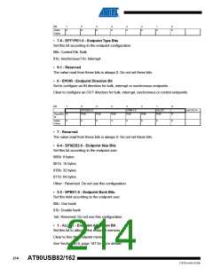
Bit
7
6
5
-
4
-
3
-
2
-
1
-
0
EPTYPE1:0
EPDIR
R/W
UECFG0X
Read/Wri R/W
te
R/W
R
R
R
R
R
213
7707D–AVR–07/08

 ATMEL [ ATMEL ]