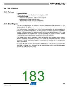
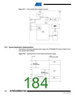
Figure 19-1. USB controller Block Diagram overview
UVCC
XTAL1
Regulator
clk
8MHz
PLL
6x
PLL clock
Prescaler
UCAP
clk
48MHz
CPU
D-
DPLL
Clock
Recovery
D+
USB
Interface
On-Chip
USB DPRAM
19.3 Typical Application Implementation
Depending on the target application power supply, the AT90USB82/162 requires different hard-
ware typical implementations.
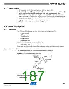
Figure 19-2. Operating modes versus frequency and power-supply
Max
VCC (V)
Operating Frequency (MHz)
5.5
16 MHz
USB compliant,
4.5
with internal regulator
4.0
3.6
8 MHz
USB compliant,
without internal regulator
3.0
2.7
USB not operational
2 MHz
VCC min
0
184
AT90USB82/162
7707D–AVR–07/08

 ATMEL [ ATMEL ]