• the USB controller clock is stopped in order to minimize the power consumption
(FRZCLK=1),
• the USB controller is disabled,
• USB is in the suspend mode,
• the Device USB controllers internal state is reset.
• The DPACC bit and the DPADD10:0 field can be set by software. The DPRAM is not cleared.
• The SPDCONF bits can be set by software.
After setting USBE, the USB Controller enters in the Device state.
The USB Controller can at any time be ‘stopped’ by clearing USBE. In fact, clearing USBE acts
as an hardware reset on the USB macro.
19.4.3
Interrupts
Two interrupts vectors are assigned to USB controller.
Figure 19-7. USB Interrupt System
USB General
Interrupt Vector
USB Device
Interrupt
USB Endpoint/Pipe
Interrupt Vector
Endpoint
Interrupt
The macro distinguishes between USB General events in opposition with USB Endpoints events
that are relevant with data transfers relatives to each endpoint.
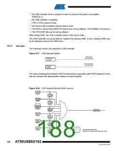
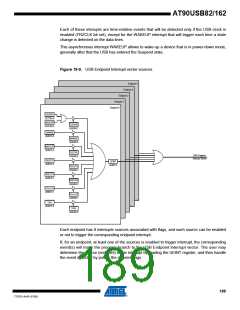
Figure 19-8. USB General interrupt vector sources
UPRSMI
UDINT.6
UPRSME
UDIEN.6
EORSMI
UDINT.5
EORSME
UDIEN.5
WAKEUPI
UDINT.4
USB General
Interrupt Vector
WAKEUPE
UDIEN.4
EORSTI
UDINT.3
EORSTE
UDIEN.3
SOFI
UDINT.2
SOFE
UDIEN.2
SUSPI
Asynchronous Interrupt source
(allows the CPU to wake up from power down mode)
UDINT.0
SUSPE
UDIEN.0
188
AT90USB82/162
7707D–AVR–07/08

 ATMEL [ ATMEL ]