AT90USB82/162
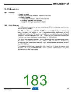
19.3.3
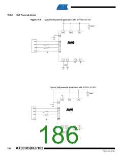
Design guidelines
• Serial resistors on USB Data lines must have 22 Ohms value (+/- 5%).
• Traces from the input USB receptable (or from the cable connection in the case of a tethered
device) to the USB microcontroller pads should be as short as possibles, and follow
differential traces routing rules (same length, as near as possible, avoid vias accumulation).
• Voltage transcient / ESD suppressors may also be used to prevent USB pads to be damaged
by external disturbances.
• Ucap capacitor should be 1µF (+/- 10%) for correct operation.
• A 10µF capacitor is highly recommended on VBUS line
19.4 General Operating Modes
19.4.1
Introduction
The USB controller is disabled and reset after a hardware reset generated by:
– Power on reset
– External reset
– Watchdog reset
– Brown out reset
– debugWIRE reset
But another available and optionnal reset source is :
– USB End Of Reset
In this case, the USB controller is reset, but not disabled (so that the device remains attached).
19.4.2
Power-on and reset
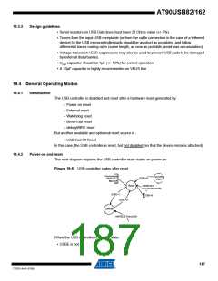
The next diagram explains the USB controller main states on power-on:
Figure 19-6. USB controller states after reset
Clockstopped
FRZCLK=1
Mac rooff
<anyother
state>
USBE=0
Reset
HWRESET
(exceptedfromEOR)
USBE=1
USBE=0
USBE=0
Device
HW RESETfromEOR
When the USB controller is in reset state:
• USBE is not set
187
7707D–AVR–07/08

 ATMEL [ ATMEL ]