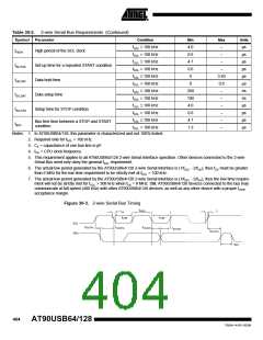
Table 30-2. 2-wire Serial Bus Requirements (Continued)
Symbol Parameter
Condition
Min
4.0
0.6
4.7
0.6
0
Max
–
Units
µs
µs
µs
µs
µs
µs
ns
ns
µs
µs
µs
µs
fSCL ≤ 100 kHz
fSCL > 100 kHz
fSCL ≤ 100 kHz
tHIGH
High period of the SCL clock
Set-up time for a repeated START condition
Data hold time
–
–
tSU;STA
tHD;DAT
tSU;DAT
tSU;STO
tBUF
f
SCL > 100 kHz
–
fSCL ≤ 100 kHz
fSCL > 100 kHz
fSCL ≤ 100 kHz
fSCL > 100 kHz
fSCL ≤ 100 kHz
3.45
0.9
–
0
250
100
4.0
0.6
4.7
1.3
Data setup time
–
–
Setup time for STOP condition
f
SCL > 100 kHz
–
fSCL ≤ 100 kHz
–
Bus free time between a STOP and START
condition
fSCL > 100 kHz
–
Notes: 1. In AT90USB64/128, this parameter is characterized and not 100% tested.
2. Required only for fSCL > 100 kHz.
3. Cb = capacitance of one bus line in pF.
4. fCK = CPU clock frequency
5. This requirement applies to all AT90USB64/128 2-wire Serial Interface operation. Other devices connected to the 2-wire
Serial Bus need only obey the general fSCL requirement.
6. The actual low period generated by the AT90USB64/128 2-wire Serial Interface is (1/fSCL - 2/fCK), thus fCK must be greater
than 6 MHz for the low time requirement to be strictly met at fSCL = 100 kHz.
7. The actual low period generated by the AT90USB64/128 2-wire Serial Interface is (1/fSCL - 2/fCK), thus the low time require-
ment will not be strictly met for fSCL > 308 kHz when fCK = 8 MHz. Still, AT90USB64/128 devices connected to the bus may
communicate at full speed (400 kHz) with other AT90USB64/128 devices, as well as any other device with a proper tLOW
acceptance margin.
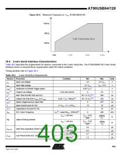
Figure 30-3. 2-wire Serial Bus Timing
t
HIGH
t
t
r
of
t
t
LOW
LOW
SCL
SDA
t
t
t
HD;DAT
SU;STA
HD;STA
t
SU;DAT
t
SU;STO
t
BUF
404
AT90USB64/128
7593A–AVR–02/06

 ATMEL [ ATMEL ]