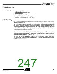
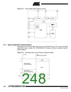
Figure 21-1. USB controller Block Diagram overview
UVCC
AVCC
XTAL1
clk
2MHz
PLL
24x
PLL clock
Prescaler
USB Regulator
UCAP
clk
48MHz
CPU
D-
DPLL
Clock
Recovery
D+
USB
Interface
VBUS
On-Chip
USB DPRAM
UID
21.3 Typical Application Implementation
Depending on the USB operating mode (Device only, Reduced Host or OTG mode) and target
application power supply, the AT90USB64/128 requires different hardware typical
implementations.
Figure 21-2. Operating modes versus frequency and power-supply
VCC (V)
Max
Operating Frequency (MHz)
5.5
4.5
16 MHz
USB operationnal
with internal regulator
8 MHz
3.4
USB operationnal
without internal regulator
3.0
2.7
USB not operationnal
2 MHz
VCC min
0
248
AT90USB64/128
7593A–AVR–02/06

 ATMEL [ ATMEL ]