• The ID bit is cleared by hardware when a low level has been detected on the ID pin. The
Device controller is then disabled and the Host controller enabled.
The software anyway has to select the mode (Host, Device) in order to access to the Device
controller registers or to the Host controller registers, which are multiplexed. For example, even
if the USB controller has detected a Device mode (pin ID high), the software shall select the
device mode (bit HOST cleared), otherwise it will access to the host registers. This is also true
for the Host mode.
21.4.2
Power-on and reset
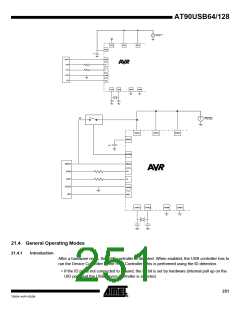
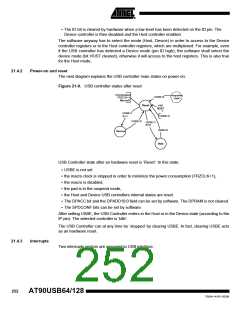
The next diagram explains the USB controller main states on power-on:
Figure 21-9. USB controller states after reset
Clockstopped
FRZCLK=1
<anyother
state>
USBE=0
Mac rooff
Reset
HW
RESET
USBE=1
ID=1
USBE=0
USBE=0
USBE=1
ID=0
USBE=0
Device
Host
USB Controller state after an hardware reset is ‘Reset’. In this state:
• USBE is not set
• the macro clock is stopped in order to minimize the power consumption (FRZCLK=1),
• the macro is disabled,
• the pad is in the suspend mode,
• the Host and Device USB controllers internal states are reset.
• The DPACC bit and the DPADD10:0 field can be set by software. The DPRAM is not cleared.
• The SPDCONF bits can be set by software.
After setting USBE, the USB Controller enters in the Host or in the Device state (according to the
IP pin). The selected controller is ‘Idle’.
The USB Controller can at any time be ‘stopped’ by clearing USBE. In fact, clearing USBE acts
as an hardware reset.
21.4.3
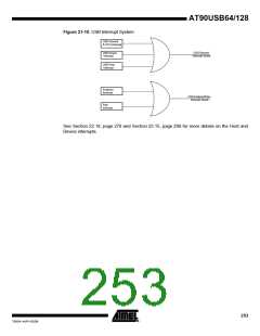
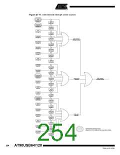
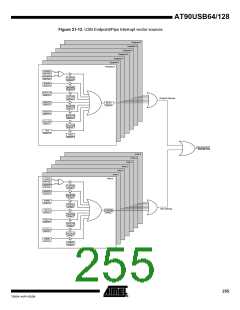
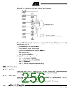
Interrupts
Two interrupts vectors are assigned to USB interface.
252
AT90USB64/128
7593A–AVR–02/06

 ATMEL [ ATMEL ]