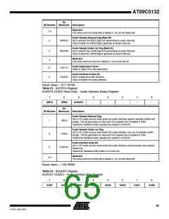
Figure 14-6. Voice or Sound Mode Audio Flows
Voice/Song Mode
Configuration
Audio Interrupt
Service Routine
Wait for DAC
Enable Time
Program Audio Clock
Sample Request?
SREQ = 1?
Configure Interface
HLR = X
DSIZ = X
POL = X
JUST4:0 = XXXXXb
Load 8 Samples in the
Audio Buffer
Load 4 Samples in the
Audio Buffer
Under-run Condition1
DUP1:0 = XX
Enable Interrupt
Set MSREQ & MUDRN1
EAUD = 1
Enable DAC System
Clock
AUDEN = 1
Note:
1. An under-run occurrence signifies that the C51 core did not respond to the previous sample request interrupt. It may never
occur for a correct voice/sound generation. It is the user’s responsibility to mask it or not.
14.7 Registers
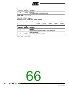
Table 51. AUDCON0 Register
AUDCON0 (S:9Ah) – Audio Interface Control Register 0
7
6
5
4
3
2
1
DSIZ
0
JUST4
JUST3
JUST2
JUST1
JUST0
POL
HLR
Bit
Bit Number Mnemonic Description
Audio Stream Justification Bits
7-3
2
JUST4:0
POL
Refer to Section "Data Converter", page 61 for bits description.
DSEL Signal Output Polarity
Set to output the left channel on high level of DSEL output (PCM mode).
Clear to output the left channel on the low level of DSEL output (I2S mode).
Audio Data Size
1
0
DSIZ
HLR
Set to select 32-bit data output format.
Clear to select 16-bit data output format.
High/Low Rate Bit
Set by software when the PLL clock frequency is 384·Fs.
Clear by software when the PLL clock frequency is 256·Fs.
Reset Value = 0000 1000b
Table 52. AUDCON1 Register
AUDCON1 (S:9Bh) – Audio Interface Control Register 1
7
–
6
–
5
4
3
-
2
1
0
MSREQ
MUDRN
DUP1
DUP0
AUDEN
64
AT89C5132
4173E–USB–09/07

 ATMEL [ ATMEL ]