AT89C5132
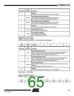
Figure 14-2. Audio Clock Generator and Symbol
AUDCLK
PLL
CLOCK
AUD
CLOCK
AUCD4:0
Audio Interface Clock
Audio Clock Symbol
PLLclk
AUCD + 1
AUDclk = ---------------------------
As soon as audio interface is enabled by setting AUDEN bit in AUDCON1 register, the master
clock generated by the PLL is output on the SCLK pin which is the DAC system clock. This clock
is output at 256 or 384 times the sampling frequency depending on the DAC capabilities. HLR bit
in AUDCON0 register must be set according to this rate for properly generating the audio bit
clock on the DCLK pin and the word selection clock on the DSEL pin. These clocks are not gen-
erated when no data is available at the data converter input.
For DAC compatibility, the bit clock frequency is programmable for outputting 16 bits or 32 bits
per channel using the DSIZ bit in AUDCON0 register (see Section "Data Converter", page 61),
and the word selection signal is programmable for outputting left channel on low or high level
according to POL bit in AUDCON0 register as shown in Figure 14-3.
Figure 14-3. DSEL Output Polarity
Left Channel
Left Channel
Right Channel
Right Channel
POL = 0
POL = 1
14.3 Data Converter
The data converter block converts the audio stream input from the 16-bit parallel format to a
serial format. For accepting all PCM formats and I2S format, JUST4:0 bits in AUDCON0 register
are used to shift the data output point. As shown in Figure 14-4, these bits allow MSB justifica-
tion by setting JUST4:0 = 00000, LSB justification by setting JUST4:0 = 10000, I2S Justification
by setting JUST4:0 = 00001, and more than 16-bit LSB justification by filling the low significant
bits with logic 0.
Table 49. DAC Format Programing Examples
DAC Format
POL
DSIZ
JUST4:0
00001
00001
00000
01110
16-bit I2S
0
0
1
1
1
1
0
1
0
1
1
1
> 16-bit I2S
16-bit PCM
18-bit PCM LSB justified
20-bit PCM LSB justified
20-bit PCM MSB justified
01100
00000
61
4173E–USB–09/07

 ATMEL [ ATMEL ]