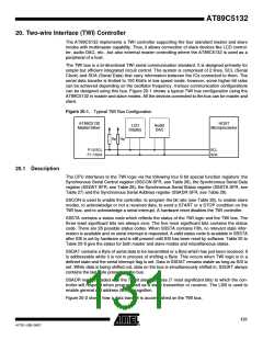
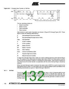
Figure 20-2. Complete Data Transfer on TWI Bus
SDA
MSB
Slave Address
R/W ACK
direction signal
Nth data Byte
ACK
signal
from
bit
8
from
receiver
receiver
1
2
9
1
2
8
9
SCL
S
P/S
Clock Line Held Low While Serial Interrupts Are Serviced
The four operating modes are:
•
•
•
•
Master transmitter
Master receiver
Slave transmitter
Slave receiver
Data transfer in each mode of operation are shown in Figure 20-3 through Figure 20-6. These
figures contain the following abbreviations:
A
Acknowledge bit (low level at SDA)
Not acknowledge bit (high level on SDA)
8-bit data Byte
A
Data
S
START condition
P
STOP condition
MR
MT
SLA
GCA
R
Master Receive
Master Transmit
Slave Address
General Call Address (00h)
Read bit (high level at SDA)
Write bit (low level at SDA)
W
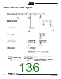
In Figure 20-3 through Figure 20-6, circles are used to indicate when the serial interrupt flag is
set. The numbers in the circles show the status code held in SSSTA. At these points, a service
routine must be executed to continue or complete the serial transfer. These service routines are
not critical since the serial transfer is suspended until the serial interrupt flag is cleared by
software.
When the serial interrupt routine is entered, the status code in SSSTA is used to branch to the
appropriate service routine. For each status code, the required software action and details of the
following serial transfer are given in Table 20 through Table 20-6.
20.1.1
Bit Rate
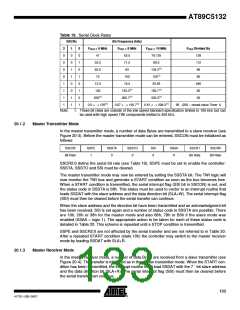
The bit rate can be selected from seven predefined bit rates or from a programmable bit rate
generator using the SSCR2, SSCR1, and SSCR0 control bits in SSCON (see Table 26). The
predefined bit rates are derived from the peripheral clock (FPER) issued from the Clock Controller
block as detailed in Section "Oscillator", page 12, while bit rate generator is based on timer 1
overflow output.
132
AT89C5132
4173E–USB–09/07

 ATMEL [ ATMEL ]