AT89C5132
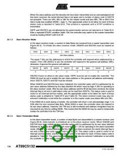
If the SSAA bit is reset during a transfer, the controller will transmit the last Byte of the transfer
and enter state C0h or C8h. The controller is switched to the not addressed slave mode and will
ignore the master receiver if it continues the transfer. Thus the master receiver receives all 1’s
as serial data. While SSAA is reset, the controller does not respond to its own slave address.
However, the TWI bus is still monitored and address recognition may be resumed at any time by
setting SSAA. This means that the SSAA bit may be used to temporarily isolate the controller
from the TWI bus.
20.1.6
Miscellaneous States
There are 2 SSSTA codes that do not correspond to a defined TWI hardware state (see
Table 25). These are discussed below.
Status F8h indicates that no relevant information is available because the serial interrupt flag is
not yet set. This occurs between other states and when the controller is not involved in a serial
transfer.
Status 00h indicates that a bus error has occurred during a serial transfer. A bus error is caused
when a START or a STOP condition occurs at an illegal position in the format frame. Examples
of such illegal positions are during the serial transfer of an address Byte, a data Byte, or an
acknowledge bit. When a bus error occurs, SSI is set. To recover from a bus error, the SSSTO
flag must be set and SSI must be cleared. This causes the controller to enter the not addressed
slave mode and to clear the SSSTO flag (no other bits in S1CON are affected). The SDA and
SCL lines are released and no STOP condition is transmitted.
Note:
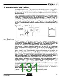
The TWI controller interfaces to the external TWI bus via 2 port 1 pins: P1.6/SCL (serial clock line)
and P1.7/SDA (serial data line). To avoid low level asserting and conflict on these lines when the
TWI controller is enabled, the output latches of P1.6 and P1.7 must be set to logic 1.
135
4173E–USB–09/07

 ATMEL [ ATMEL ]