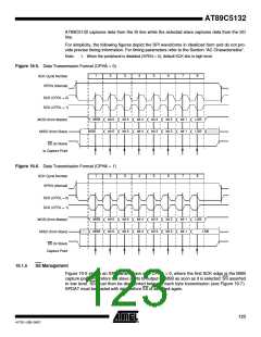
Figure 19-6 shows an SPI transmission with CPHA = 1, where the first SCK edge is used by the
slave as a start of transmission signal. Therefore SS may remain asserted between each byte
transmission (see Figure 19-7).
Figure 19-7. SS Timing Diagram
Byte 1
Byte 2
Byte 3
SI/SO
SS (CPHA = 0)
SS (CPHA = 1)
19.1.6
Error Conditions
The following flags signal the SPI error conditions:
• MODF in SPSTA signals a mode fault.
MODF flag is relevant only in master mode when SS usage is enabled (SSDIS bit cleared).
It signals when set that another master on the bus has asserted SS pin and so, may create
a conflict on the bus with two masters sending data at the same time.
A mode fault automatically disables the SPI (SPEN cleared) and configures the SPI in slave
mode (MSTR cleared).
MODF flag can trigger an interrupt as explained in Section "Interrupt", page 124.
MODF flag is cleared by reading SPSTA and re-configuring SPI by writing to SPCON.
•
WCOL in SPSTA signals a write collision.
WCOL flag is set when SPDAT is loaded while a transfer is on-going. In this case, data is not
written to SPDAT and transfer continues uninterrupted. WCOL flag does not trigger any
interrupt and is relevant jointly with SPIF flag.
WCOL flag is cleared after reading SPSTA and writing new data to SPDAT while no transfer
is ongoing.
19.2 Interrupt
The SPI handles two interrupt sources; the “end of transfer” and the “mode fault” flags.
As shown in Figure 19-8 these flags are combined together to appear as a single interrupt
source for the C51 core. The SPIF flag is set at the end of an 8-bit shift in and out and is cleared
by reading SPSTA and then reading from or writing to SPDAT.
The MODF flag is set in case of mode fault error and is cleared by reading SPSTA and then writ-
ing to SPCON.
The SPI interrupt is enabled by setting ESPI bit in IEN1 register. This assumes interrupts are
globally enabled by setting EA bit in IEN0 register.
Figure 19-8. SPI Interrupt System
SPIF
SPSTA.7
SPI Controller
Interrupt Request
MODF
SPSTA.4
ESPI
IEN1.2
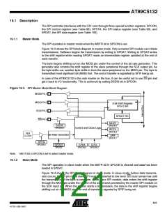
19.3 Configuration
The SPI configuration is made through SPCON.
124
AT89C5132
4173E–USB–09/07

 ATMEL [ ATMEL ]