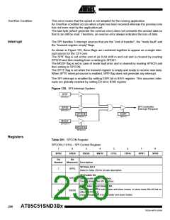
Access Cycles
The AT85C51SND3Bx enables connection of LCD controller with normalized 6800 and
8080 interface as shown in Figure 127 and Figure 128, but also enables connection of
LCD controller with non normalized 6800 and 8080 interface as shown in Figure 129
and Figure 130.
This is achieved by setting or clearing CYCT bit in LCDCON1 for selecting non normal-
ized or normalized access type.
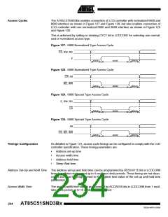
Figure 127. 6800 Normalized Type Access Cycle
CS, RW, RS
E
ADSUH
ACCW
ADSUH
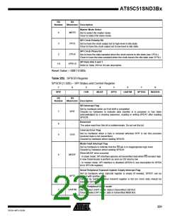
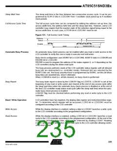
Figure 128. 8080 Normalized Type Access Cycle
CS, A0
RD, WR
ADSUH
ACCW
ADSUH
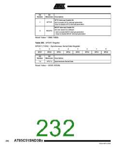
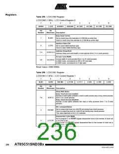
Figure 129. 6800 Special Type Access Cycle
E, RW, RS
CS
ADSUH
ACCW
ADSUH
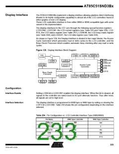
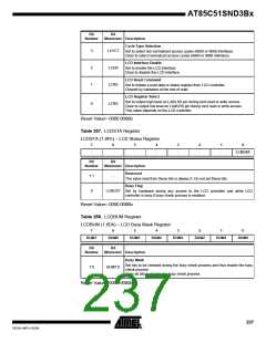
Figure 130. 8080 Special Type Access Cycle
A0
CS, RD, WR
ADSUH
ACCW
ADSUH
Timings Configuration
As detailed in Figure 131, access cycle timing can be configured to comply with the LCD
controller specification. These timing parameters are:
•
•
•
•
Address set-up time
Access width time
Address hold time
Sleep Wait time
Address Set-Up and Hold Time
Access Width Time
The address set-up and hold time can be programmed by ADSUH1:0 bits in LCDCON0
from 1 oscillator clock period up to 4 oscillator clock periods. These timing are not disso-
ciated and must be programmed to the highest time value of the set-up and hold time
parameters.
The access width time can be programmed by ACCW3:0 bits in LCDCON0 from 1 oscil-
lator clock period up to 16 oscillator clock period.
234
AT85C51SND3Bx
7632A–MP3–03/06

 ATMEL [ ATMEL ]