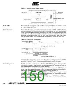
Audio Codec
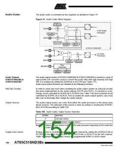
The audio codec is controlled by four registers as detailed in Figure 74:
Figure 74. Audio Codec Block Diagram
ACORG.4:0
AORG4:0
D
1
OUTR
A
A
0
From Audio
Processor
AODRV
ACCON.2
D
1
0
OUTL
AOLG4:0
ACOLG.4:0
AOSSEL
ACCON.1
AILPG
ACIPG.3
AT85C51SND3B2
&
LINR
0
A
Σ
To Audio
Processor
LINL
1
D
MICIN
AISSEL AIPG2:0
ACCON.4
ACIPG.2:0
Bias
Generator
MICBIAS
AMBEN
ACCON.5
AMBVS
ACCON.6
Audio Outputs
AT85C51SND3B2 &
AT85C51SND3B3
The audio output system of AT85C51SND3B2 & AT85C51SND3B3 is based on a pair of
sigma-delta D/A converter used to convert the audio data with high linearity and high
S/N. It is enabled by setting the AOEN bit in ACCON (see Table 177).
Audio input system features are detailed in the following sections.
Anti-Pop Circuitry
Output Sources
In order to avoid any noise when enabling the audio output system an anti-pop circuitry
has been implemented on the audio outputs (OUTR and OUTL). It consists in a dis-
charge circuit controlled by AODIS bit in ACAUX (see Table 178) and a preload circuit
controlled by AOPRE bit in ACAUX. Prior to enable the audio output system, user must
take care to discharge then charge the audio outputs.
The audio output source can come from either the audio processor or the stereo lines
Inputs sources. The selection of the source is done by setting or clearing the AOSSEL
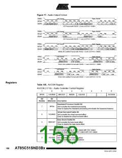
bit in ACCON according to Table 156.
Table 156. Audio Codec Output Source Selection
AOSSEL
Selection
0
1
Line Input (stereo)
Audio Processor (mono or stereo)(1)
Note:
1. Stereo or mono choice is done by the audio processor depending on the audio flow
under decoding.
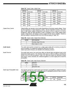
Output Gain Control
Analog volume is controlled separately on both channel by setting the AORG4:0 bits in
ACORG for the right channel and the AOLG4:0 bits in ACOLG for the left channel.
Table 157 shows the gain value versus the programmed AORG or AOLG value.
154
AT85C51SND3Bx
7632A–MP3–03/06

 ATMEL [ ATMEL ]