AT85C51SND3Bx
In order to avoid any spurious interrupts on the CPU side when a data transfer with the
data flow controller is established, APREQE and APRDYE must be left cleared.
Digital Audio Processor
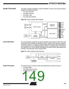
The digital audio processor is based on a proprietary digital signal processor. It provides
capability to decode many digital audio formats like MP3, WMA, G726, RAW PCM…
and to encode some digital audio formats like G726, RAW PCM…
Processor Initialization
Prior to enable the digital audio processor by setting the DAPEN bit in APCON1(1), the
C51 must load the processor codec firmware which is the stream decoder or encoder.
This can be achieved by setting APLOAD(2) bit in APCON1 and loading data using the
C51 (through APDAT) or the DFC as detailed in the Section “Audio Buffer”. As soon as
the codec firmware is fully loaded, the digital audio processor can be enabled with the
effect to start the codec execution. Then the audio stream type that can be decoded or
encoded depends on the codec firmware loaded.
Note:
1. Clearing DAPEN bit resets the code writing pointer address to 0000h.
2. Toggling APLOAD bit leaves the code writing pointer address unchanged.
Processor Interface
The C51 interfacing the processor through 3 registers: APCON0 by using APCMD6:0
bits, APSTA and APINT by using APEVTI bit. APCMD field is used to send commands
to the processor while APSTA and APEVTI are used by the processor to trigger an
event or give a status to the C51. Command and status relies on the processor codec
firmware and are beyond the scope of this document.
Play Time
In order to allow time stamping in case of synchronized lyrics (karaoke mode), a 24-bit
time stamp is provided by APTIM2:0 registers with APTIM2 being the MSB and APTIM0
being the LSB. Time unit is millisecond.
Getting the time value is done by reading first APTIM0, then APTIM1 and APTIM2. The
counter value is latched during read sequence, avoiding bad reading if increment
occurs.
Initializing the time value is done by writing first APTIM0, then APTIM1 and APTIM2.
The counter is updated after writing last time stamp byte APTIM2.
Time value is automatically updated by the audio processor in case of fast for-
ward/rewind operating mode. Time value is reset when operating mode switches from
Stop to Play mode and frozen when in Pause mode.
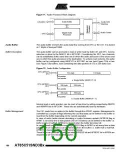
Audio Stream Interface
Every codec firmwares (decoder or encoder) share a set of registers allowing to perform
configuration and control and to get status from the decoding or encoding process. This
set of registers is composed of ASCON, the audio stream control register and ASSTA0
ASSTA1 and ASSTA2, the audio stream status registers. The content of these registers
depends on the codec firmware loaded and are beyond the scope of this document.
Baseband Processor
Several digital baseband treatments can be applied to the digital audio signal immedi-
ately before internal or external D/A conversion:
•
•
•
•
•
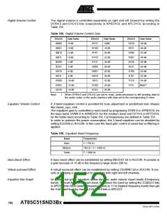
Digital volume control
3-bands equalizer
Bass boost effect
Virtual surround effect
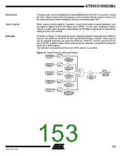
Mixing mode
The baseband processor is enabled by setting BPEN bit in AUCON. When disabled
(BPEN bit cleared) all of the above treatments are disabled.
151
7632A–MP3–03/06

 ATMEL [ ATMEL ]