AT85C51SND3Bx
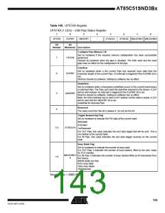
Table 145. UPSTAX Register
UPSTAX (1.CEh) – USB Pipe Status Register
7
6
5
4
3
2
1
0
CFGOK
OVERFI
UNDERFI
-
DTSEQ1
DTSEQ0 NBUSYBK1 NBUSYBK0
Bit
Bit
Number
Mnemonic Description
Configure Pipe Memory OK
Set by hardware if the required memory configuration has been successfully
performed.
Cleared by hardware when the pipe is disabled. The USB reset and the reset
pipe have no effect on the configuration of the pipe.
7
6
CFGOK
OVERFI
Overflow
Set by hardware when a the current Pipe has received more data than the
maximum length of the current Pipe. An interrupt is triggered if the FLERRE bit is
set.
Shall be cleared by software. Setting by software has no effect.
Underflow
Set by hardware when a transaction underflow occurs in the current isochronous
or interrupt Pipe. The Pipe can’t send the data flow required by the device. A ZLP
will be sent instead. An interrupt is triggered if the FLERRE bit is set.
Shall be cleared by software. Setting by software has no effect.
Note: the Host controller has to send a OUT packet, but the bank is empty. A ZLP
will be sent and the UNDERFI bit is set
5
4
UNDERFI
underflow for interrupt Pipe:
Reserved
-
The value read from this bit is always 0. Do not set this bit.
Toggle Sequencing Flag
Set by hardware to indicate the PID data of the current bank:
00bData0
01bData1
3-2
DTSEQ1:0
1xbReserved.
For OUT Pipe, this value indicates the next data toggle that will be sent. This is
not relative to the current bank.
For IN Pipe, this value indicates the last data toggle received on the current
bank.
Busy Bank Flag
Set by hardware to indicate the number of busy bank.
For OUT Pipe, it indicates the number of busy bank(s), filled by the user, ready
for OUT transfer.
NBUSYBK1:
0
For IN Pipe, it indicates the number of busy bank(s) filled by IN transaction from
the Device.
1-0
00bAll banks are free
01b1 busy bank
10b2 busy banks
11bReserved.
Reset Value = 0000 0000b
143
7632A–MP3–03/06

 ATMEL [ ATMEL ]