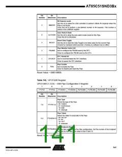
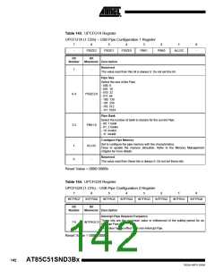
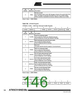
Table 143. UPCFG1X Register
UPCFG1X (1.CDh) – USB Pipe Configuration 1 Register
7
6
5
4
3
2
1
0
-
PSIZE2
PSIZE1
PSIZE0
PBK1
PBK0
ALLOC
-
Bit
Bit
Number
Mnemonic Description
Reserved
7
-
The value read from this bit is always 0. Do not set this bit.
Pipe Size
Select the size of the Pipe:
- 000: 8
- 001: 16
- 010: 32
- 011: 64
6-4
PSIZE2:0
- 100: 128
- 101: 256
- 110: 512
- 111: 1024
Pipe Bank
Select the number of bank to declare for the current Pipe.
- 00: 1 bank
- 01: 2 banks
- 10: invalid
- 11: invalid
3-2
PBK1:0
Configure Pipe Memory
Set to configure the pipe memory with the characteristics.
Clear to update the memory allocation. Refer to the Memory Management
chapter for more details.
1
0
ALLOC
-
Reserved
The value read from these bits is always 0. Do not set these bits.
Reset Value = 0000 0000b
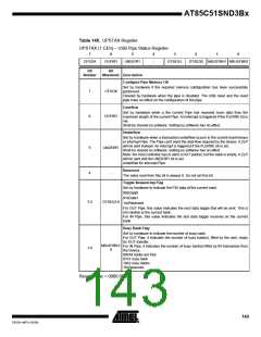
Table 144. UPCFG2X Register
UPCFG2X (1.CFh) – USB Pipe Configuration 2 Register
7
6
5
4
3
2
1
0
INTFRQ7
INTFRQ6
INTFRQ5
INTFRQ4
INTFRQ3
INTFRQ2
INTFRQ1
INTFRQ0
Bit
Bit
Number
Mnemonic Description
Interrupt Pipe Request Frequency
These bits are the maximum value in millisecond of the pulling period for an
Interrupt Pipe.
7-0
INTFRQ7:0
This value has no effect for a non-Interrupt Pipe.
Reset Value = 0000 0000b
142
AT85C51SND3Bx
7632A–MP3–03/06

 ATMEL [ ATMEL ]