AT8xC51SND2C
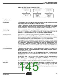
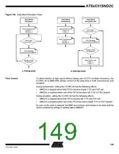
Figure 96. Data Controller Configuration Flows
Data Stream
Configuration
Data Single Block
Configuration
Data Multi-Block
Configuration
Configure Format
Configure Format
DFMT = 1
Configure Format
DFMT = 1
DFMT = 0
MBLOCK = 0
MBLOCK = 1
BLEN3:0 = XXXXb
BLEN3:0 = XXXXb
Data Transmitter
Configuration
For transmitting data to the card user must first configure the data controller in transmis-
sion mode by setting the DATDIR bit in MMCON1 register.
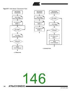
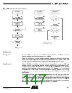
Figure 97 summarizes the data stream transmission flows in both polling and interrupt
modes while Figure 98 summarizes the data block transmission flows in both polling
and interrupt modes, these flows assume that block length is greater than 16 data.
Data Loading
Data is loaded in the FIFO by writing to MMDAT register. Number of data loaded may
vary from 1 to 16 Bytes. Then if necessary (more than 16 Bytes to send) user must wait
that one FIFO becomes empty (F1EI or F2EI set) before loading 8 new data.
Data Transmission
Transmission is enabled by setting and clearing DATEN bit in MMCON1 register.
Data is transmitted immediately if the response has already been received, or is delayed
after the response reception if its status is correct. In both cases transmission is delayed
if a card sends a busy state on the data line until the end of this busy condition.
According to the MMC specification, the data transfer from the host to the card may not
start sooner than 2 MMC clock periods after the card response was received (formally
NWR parameter). To address all card types, this delay can be programmed using
DATD1:0 bits in MMCON2 register from 3 MMC clock periods when DATD1:0 bits are
cleared to 9 MMC clock periods when DATD1:0 bits are set, by step of 2 MMC clock
periods.
End of Transmission
The end of a data frame (block or stream) transmission is signalled to you by the EOFI
flag in MMINT register. This flag may generate an MMC interrupt request as detailed in
Section "Interrupt", page 150.
In data stream mode, EOFI flag is set, after reception of the End bit. This assumes user
has previously sent the STOP command to the card, which is the only way to stop
stream transfer.
In data block mode, EOFI flag is set, after reception of the CRC status token (see
Figure 88). 2 other flags in MMSTA register: DATFS and CRC16S report a status on the
frame sent. DATFS indicates if the CRC status token format is correct or not, and
CRC16S indicates if the card has found the CRC16 of the block correct or not.
Busy Status
As shown in Figure 88 the card uses a busy token during a block write operation. This
busy status is reported to you by the CBUSY flag in MMSTA register and by the MCBI
flag in MMINT which is set every time CBUSY toggles, i.e. when the card enters and
exits its busy state. This flag may generate an MMC interrupt request as detailed in Sec-
tion "Interrupt", page 150.
145
4341D–MP3–04/05

 ATMEL [ ATMEL ]