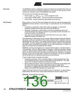
required, to provide 8 (eight) clock cycles for the card to complete the operation
before shutting down the clock. Following is a list of the various bus transactions:
•
•
•
•
•
A command with no response. 8 clocks after the host command End bit.
A command with response. 8 clocks after the card command End bit.
A read data transaction. 8 clocks after the End bit of the last data block.
A write data transaction. 8 clocks after the CRC status token.
The host is allowed to shut down the clock of a “busy” card. The card will complete
the programming operation regardless of the host clock. However, the host must
provide a clock edge for the card to turn off its busy signal. Without a clock edge the
card (unless previously disconnected by a deselect command-CMD7) will force the
MDAT line down, forever.
Description
The MMC controller interfaces to the C51 core through the following eight special func-
tion registers:
MMCON0, MMCON1, MMCON2, the three MMC control registers (see Table 145 to
Table 153); MMSTA, the MMC status register (see Table 148); MMINT, the MMC inter-
rupt register (see Table 149); MMMSK, the MMC interrupt mask register (see
Table 150); MMCMD, the MMC command register (see Table 151); MMDAT, the MMC
data register (see Table 152); and MMCLK, the MMC clock register (see Table 153).
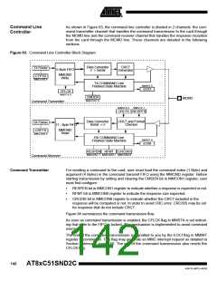
As shown in Figure 90, the MMC controller is divided in four blocks: the clock generator
that handles the MCLK (formally the MMC CLK) output to the card, the command line
controller that handles the MCMD (formally the MMC CMD) line traffic to or from the
card, the data line controller that handles the MDAT (formally the MMC DAT) line traffic
to or from the card, and the interrupt controller that handles the MMC controller interrupt
sources. These blocks are detailed in the following sections.
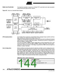
Figure 90. MMC Controller Block Diagram
MCLK
OSC
CLOCK
Clock
Generator
Command Line
Controller
MCMD
MMC
Interrupt
Request
Interrupt
Controller
Data Line
Controller
MDAT
Internal
8
Bus
Clock Generator
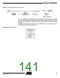
The MMC clock is generated by division of the oscillator clock (FOSC) issued from the
Clock Controller block as detailed in Section "Oscillator", page 12. The division factor is
given by MMCD7:0 bits in MMCLK register, a value of 0x00 stops the MMC clock.
Figure 91 shows the MMC clock generator and its output clock calculation formula.
140
AT8xC51SND2C
4341D–MP3–04/05

 ATMEL [ ATMEL ]