AT8xC51SND2C
Table 141. R3 Response Format (OCR Register)
Bit Position
Width (bits)
Value
47
1
46
1
[45:40]
6
[39:8]
[7:1]
7
0
32
-
1
‘0’
‘0’
‘111111’
‘1111111’
‘1’
Transmission
bit
OCR
register
Start bit
Reserved
Reserved
End bit
Description
Table 142. R4 Response Format (Fast I/O)
Bit Position
Width (bits)
Value
47
1
46
1
[45:40]
6
[39:8]
[7:1]
0
32
-
7
-
1
‘0’
‘0’
‘100111’
‘1’
Transmission
bit
Command
Index
Start bit
Argument
CRC7
End bit
Description
Table 143. R5 Response Format
Bit Position
Width (bits)
Value
47
1
46
1
[45:40]
6
[39:8]
[7:1]
0
32
-
7
-
1
‘0’
‘0’
‘101000’
‘1’
Transmission
bit
Command
Index
Start bit
Argument
CRC7
End bit
Description
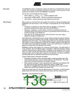
Data Packet Format
There are 2 types of data packets: stream and block. As shown in Figure 89, stream
data packets have an indeterminate length while block packets have a fixed length
depending on the block length. Each data packet is preceded by a Start bit: a low level
on MCMD line and succeeded by an End bit: a high level on MCMD line. Due to the fact
that there is no predefined end in stream packets, CRC protection is not included in this
case. The CRC protection algorithm for block data is a 16-bit CCITT polynomial.
Figure 89. Data Token Format
Sequential Data
0
0
Content
1
1
Block Data
Content
CRC
Block Length
Clock Control
The MMC bus clock signal can be used by the host to turn the cards into energy saving
mode or to control the data flow (to avoid under-run or over-run conditions) on the bus.
The host is allowed to lower the clock frequency or shut it down.
There are a few restrictions the host must follow:
•
The bus frequency can be changed at any time (under the restrictions of maximum
data transfer frequency, defined by the cards, and the identification frequency
defined by the specification document).
•
It is an obvious requirement that the clock must be running for the card to output
data or response tokens. After the last MultiMedia Card bus transaction, the host is
139
4341D–MP3–04/05

 ATMEL [ ATMEL ]