AT8xC51SND2C
Figure 83. (Multiple) Block Read Operation
Stop Command
MCMD
MDAT
Command Response
Command Response
Data Stop Operation
Data Block CRC Data Block CRC Data Block CRC
Block Read Operation
Multiple Block Read Operation
As shown in Figure 84 and Figure 85 the data write operation uses a simple busy signal-
ling of the write operation duration on the data line (MDAT).
Figure 84. Sequential Write Operation
Stop Command
MCMD
MDAT
Command Response
Command Response
Data Stream
Busy
Data Transfer Operation
Data Stop Operation
Figure 85. Multiple Block Write Operation
Stop Command
MCMD
MDAT
Command Response
Command Response
Data Block CRC Status Busy
Data Block CRC Status Busy
Data Stop Operation
Block Write Operation
Multiple Block Write Operation
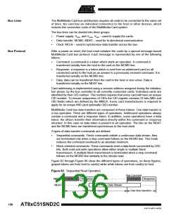
Figure 86. No Response and No Data Operation
MCMD
MDAT
Command
Command Response
No Response Operation
No Data Operation
Command Token Format
As shown in Figure 87, commands have a fixed code length of 48 bits. Each command
token is preceded by a Start bit: a low level on MCMD line and succeeded by an End bit:
a high level on MCMD line. The command content is preceded by a Transmission bit: a
high level on MCMD line for a command token (host to card) and succeeded by a 7 - bit
CRC so that transmission errors can be detected and the operation may be repeated.
Command content contains the command index and address information or parameters.
Figure 87. Command Token Format
0
1
Content
CRC
1
Total Length = 48 bits
137
4341D–MP3–04/05

 ATMEL [ ATMEL ]