AT8xC51SND2C
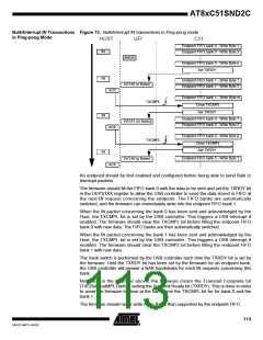
Isochronous Transactions
Isochronous OUT
Transactions in Standard
Mode
An endpoint should be first enabled and configured before being able to receive Isochro-
nous packets.
When an OUT packet is received on an endpoint, the RXOUTB0 bit is set by the USB
controller. This triggers an interrupt if enabled. The firmware has to select the corre
Bulk-outsponding endpoint, store the number of data Bytes by reading the UBYCTX
register. If the received packet is a ZLP (Zero Length Packet), the UBYCTX register
value is equal to 0 and no data has to be read.
The STLCRC bit in the UEPSTAX register is set by the USB controller if the packet
stored in FIFO has a corrupted CRC. This bit is updated after each new packet receipt.
When all the endpoint FIFO Bytes have been read, the firmware should clear the
RXOUTB0 bit to allow the USB controller to store the next OUT packet data into the
endpoint FIFO. Until the RXOUTB0 bit has been cleared by the firmware, the data sent
by the Host at each OUT transaction will be lost.
If the RXOUTB0 bit is cleared while the Host is sending data, the USB controller will
store only the remaining Bytes into the FIFO.
If the Host sends more Bytes than supported by the endpoint FIFO, the overflow data
won’t be stored, but the USB controller will consider that the packet is valid if the CRC is
correct.
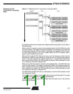
Isochronous OUT
Transactions in Ping-pong
Mode
An endpoint should be first enabled and configured before being able to receive Isochro-
nous packets.
When a OUT packet is received on the endpoint bank 0, the RXOUTB0 bit is set by the
USB controller. This triggers an interrupt if enabled. The firmware has to select the cor-
responding endpoint, store the number of data Bytes by reading the UBYCTX register. If
the received packet is a ZLP (Zero Length Packet), the UBYCTX register value is equal
to 0 and no data has to be read.
The STLCRC bit in the UEPSTAX register is set by the USB controller if the packet
stored in FIFO has a corrupted CRC. This bit is updated after each new packet receipt.
When all the endpoint FIFO Bytes have been read, the firmware should clear the
RXOUB0 bit to allow the USB controller to store the next OUT packet data into the end-
point FIFO bank 0. This action switches the endpoint bank 0 and 1. Until the RXOUTB0
bit has been cleared by the firmware, the data sent by the Host on the bank 0 endpoint
FIFO will be lost.
If the RXOUTB0 bit is cleared while the Host is sending data on the endpoint bank 0, the
USB controller will store only the remaining Bytes into the FIFO.
When a new OUT packet is received on the endpoint bank 1, the RXOUTB1 bit is set by
the USB controller. This triggers an interrupt if enabled. The firmware empties the bank
1 endpoint FIFO before clearing the RXOUTB1 bit. Until the RXOUTB1 bit has been
cleared by the firmware, the data sent by the Host on the bank 1 endpoint FIFO will be
lost.
The RXOUTB0 and RXOUTB1 bits are alternatively set by the USB controller at each
new packet receipt.
The firmware has to clear one of these 2 bits after having read all the data FIFO to allow
a new packet to be stored in the corresponding bank.
115
4341D–MP3–04/05

 ATMEL [ ATMEL ]