Suspend/Resume Management
Suspend
The Suspend state can be detected by the USB controller if all the clocks are enabled
and if the USB controller is enabled. The bit SPINT is set by hardware when an idle
state is detected for more than 3 ms. This triggers a USB interrupt if enabled.
In order to reduce current consumption, the firmware can put the USB PAD in idle mode,
stop the clocks and put the C51 in Idle or Power-down mode. The Resume detection is
still active.
The USB PAD is put in idle mode when the firmware clear the SPINT bit. In order to
avoid a new suspend detection 3ms later, the firmware has to disable the USB clock
input using the SUSPCLK bit in the USBCON Register. The USB PAD automatically
exits of idle mode when a wake-up event is detected.
The stop of the 48 MHz clock from the PLL should be done in the following order:
1. Disable of the 48 MHz clock input of the USB controller by setting to 1 the SUS-
PCLK bit in the USBCON register.
2. Disable the PLL by clearing the PLLEN bit in the PLLCON register.
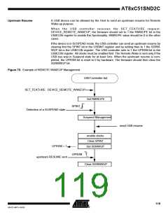
Resume
When the USB controller is in Suspend state, the Resume detection is active even if all
the clocks are disabled and if the C51 is in Idle or Power-down mode. The WUPCPU bit
is set by hardware when a non-idle state occurs on the USB bus. This triggers an inter-
rupt if enabled. This interrupt wakes up the CPU from its Idle or Power-down state and
the interrupt function is then executed. The firmware will first enable the 48 MHz gener-
ation and then reset to 0 the SUSPCLK bit in the USBCON register if needed.
The firmware has to clear the SPINT bit in the USBINT register before any other USB
operation in order to wake up the USB controller from its Suspend mode.
The USB controller is then re-activated.
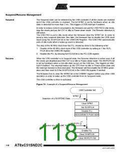
Figure 74. Example of a Suspend/Resume Management
USB Controller Init
SPINT
Detection of a SUSPEND State
Clear SPINT
Set SUSPCLK
Disable PLL
microcontroller in Power-down
WUPCPU
Detection of a RESUME State
Enable PLL
Clear SUSPCLK
Clear WUPCPU Bit
118
AT8xC51SND2C
4341D–MP3–04/05

 ATMEL [ ATMEL ]