AT8xC51SND2C
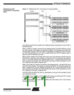
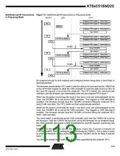
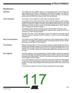
Bulk/Interrupt IN Transactions Figure 73. Bulk/Interrupt IN transactions in Ping-pong mode
in Ping-pong Mode
HOST
UFI
C51
Endpoint FIFO bank 0 - Write Byte 1
Endpoint FIFO bank 0 - Write Byte 2
IN
NACK
Endpoint FIFO bank 0 - Write Byte n
Set TXRDY
IN
Endpoint FIFO bank 1 - Write Byte 1
Endpoint FIFO bank 1 - Write Byte 2
DATA0 (n Bytes)
ACK
Endpoint FIFO bank 1 - Write Byte m
Clear TXCMPL
TXCMPL
Set TXRDY
IN
Endpoint FIFO bank 0 - Write Byte 1
Endpoint FIFO bank 0 - Write Byte 2
DATA1 (m Bytes)
ACK
Endpoint FIFO bank 0 - Write Byte p
Clear TXCMPL
TXCMPL
Set TXRDY
IN
Endpoint FIFO bank 1 - Write Byte 1
DATA0 (p Bytes)
ACK
An endpoint should be first enabled and configured before being able to send Bulk or
Interrupt packets.
The firmware should fill the FIFO bank 0 with the data to be sent and set the TXRDY bit
in the UEPSTAX register to allow the USB controller to send the data stored in FIFO at
the next IN request concerning the endpoint. The FIFO banks are automatically
switched, and the firmware can immediately write into the endpoint FIFO bank 1.
When the IN packet concerning the bank 0 has been sent and acknowledged by the
Host, the TXCMPL bit is set by the USB controller. This triggers a USB interrupt if
enabled. The firmware should clear the TXCMPL bit before filling the endpoint FIFO
bank 0 with new data. The FIFO banks are then automatically switched.
When the IN packet concerning the bank 1 has been sent and acknowledged by the
Host, the TXCMPL bit is set by the USB controller. This triggers a USB interrupt if
enabled. The firmware should clear the TXCMPL bit before filling the endpoint FIFO
bank 1 with new data.
The bank switch is performed by the USB controller each time the TXRDY bit is set by
the firmware. Until the TXRDY bit has been set by the firmware for an endpoint bank,
the USB controller will answer a NAK handshake for each IN requests concerning this
bank.
Note that in the example above, the firmware clears the Transmit Complete bit
(TXCBulk-outMPL) before setting the Transmit Ready bit (TXRDY). This is done in order
to avoid the firmware to clear at the same time the TXCMPL bit for for bank 0 and the
bank 1.
The firmware should never write more Bytes than supported by the endpoint FIFO.
113
4341D–MP3–04/05

 ATMEL [ ATMEL ]