Functional
Description
The AT7908E is an integrated device that performs serial communications according to
the CAN protocol. The CAN protocol uses a multi-master bus configuration to transfer
data packets between nodes on a network. It supports both, standard and extended,
message frame formats as CAN Specification 2.0B. It can transmit and receive with 29
identifier bits and it can filter the first eleven bits of the receiving message (the filtering
function is performed only on eleven bits).
The AT7908E has one transmit buffer and three receiving buffers. The filtering function
is individual for every RX message buffer. Every RX message buffer is formed by an
identifier (29 bits long), by the data and by the status register that store the status of the
receiver buffer. The identifier permits to filter the receiving message together with the
global mask that implements the don’t care condition. A message is accepted and
stored in the RX message buffer only if the identifier of the incoming message (first
eleven bits) matches the identifier in the RX message buffer. If the receiving message
matches more than one identifier, the message is stored in the lowest numbered mes-
sage buffer.
The AT7908E implements a global acceptance-masking feature for the message
filtering.
The AT7908E was developed to have a programmable general-purpose MCU interface.
The MCU interface permits to program the internal register of the AT7908E and to read
out the status of the controller and the received messages. The schematic representa-
tion of the AT7908E is shown in Fig. 1.
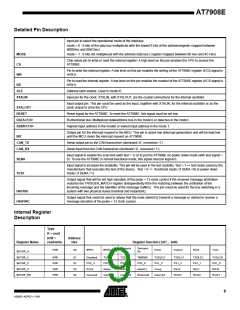
Figure 1. Block Schematic of AT7908E
Mode sena test
CS
CAN
Receiver
can_rx
Error
Counters
error counters
WR
RD
CRC
Calculator
crc_calculator
MCU
ALE
addr<7:0>
INTERFACE
Synchronizer
data_add<7:0>
XTALIN
reset
Stuff
Handler
CAN
Transmitter
can_tx
Error_frame_gen
xtalout
int
cantx canrx hatrig hasync
To transmit a CAN message, the MCU must write in the interface internal registers the
data and the configuration signals. The message bus (0 to 101) goes to can_tx that
generates the output signal to the transceiver can_tx and the signals for crc_calculator
and for error_counters.
The crc_calculator block calculates the CRC on the received message and, if the CAN
is in Transmission State, sends the CRC to can_tx. If the CAN is receiving the mes-
sage, the CRC is sent to can_rx (CRC<0:14>) that checks if the calculated CRC
matches the received CRC.
6
AT7908E
4268D–AERO–11/09

 ATMEL [ ATMEL ]