Application Notes
ATH Series of Wide-Output Adjust Power
Modules (3.3/5-V Input)
Notes
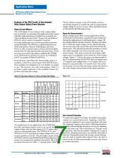
Pre-Bias Startup Capability
Only selected products in the ATH family incorporate this
capability. Consult Table 3-1 to identify which products
are compliant.
1. Startup is the relatively short period (approx. 10 ms)
prior to the output voltage rising. The startup period
immediately follows either the application of a valid
input source voltage, or the release of a ground signal
at the Inhibit pin.
A pre-bias startup condition occurs as a result of an external
voltage being present at the output of a power module prior
to its output becoming active. This often occurs in com-
plex digital systems when current from another power
source is backfed through a dual-supply logic component,
such as an FPGA or ASIC. Another path might be via
clamp diodes as part of a dual-supply power-up sequencing
arrangement. A prebias can cause problems with power
modules that incorporate synchronous rectifiers. This is
because under most operating conditions, these types of
modules can sink as well as source output current.
2. To ensure that the regulator does not sink current when
power is first applied (even with a ground signal applied
to the Inhibit control pin), the input voltage must always
be greater than the output voltage throughout the
power-up and power-down sequence.
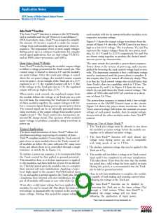
3. The Auto-Track function can be disabled at power up
by immediately applying a voltage to the module’s Track
pin that is greater than its set-point voltage. This can
be easily accomplished by connecting the Track pin to
Vin through a 1-kΩ resistor.
The ATH family of power modules incorporate synchro-
1
nous rectifiers, but will not sink current during startup ,
or whenever the Inhibit pin is held low. However, to ensure
satisfactory operation of this function, certain conditions
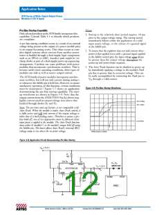
must be maintained. Figure 3-7 shows an application
Figure 3.9; Pre-Bias Startup Waveforms
2
demonstrating the pre-bias startup capability. The start-
up waveforms are shown in Figure 3-9. Note that the
output current from the ATH15T033-9xx (Io) shows neg-
ligible current until its output voltage rises above that
backfed through diodes D1 and D2.
Vin (1 V/Div)
Vo (1 V/Div)
Note: The pre-bias start-up feature is not compatible with
Auto-Track. When the module is under Auto-Track control, it
is fully active and will sink current if the output voltage is
below that of a back-feeding source. Therefore to ensure a pre-
bias hold-off, one of two approaches must be followed when
input power is applied to the module. The Auto-Track function
Io (5 A/Div)
3
must either be disabled , or the module’s output held off using
the Inhibit pin. The latter allows Auto-Track’s internal (RC)
voltage ramp to rise above the set-point voltage.
HORIZ SCALE: 5 ms/Div
Figure 3.8; Application Circuit Demonstrating Pre-Bias Startup
VIN = 3.3 V
R1
1k0
10
9
8
5
D1, D2
Track
Sense
MBR3100
Vo = 2.5 V
+
2
6
VIN
Inhibit
VO
ATH15T033-9S
PTH03010W
GND
Vadj
4
Io
3
1
7
VCCIO
VCORE
R2
2k21
+
+
CIN
COUT
330 µF
330 µF
ASIC
North America (USA): 1-888-41-ASTEC
Europe (UK): 44(1384)842-211
Asia (HK): 852-2437-9662

 ASTEC [ Astec America, Inc ]