9
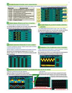
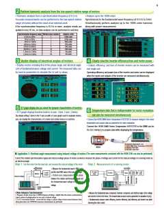
Perform harmonic analysis from the low-speed rotation range of motors
2
• Harmonic analysis from a synchronization frequency of 0.5 Hz
Accurate measurements can be performed in the low-speed rotation
range of motors without the need of an external clock.
• Analyze up to the 100th order
Synchronized to the fundamental wave frequency of 0.5 Hz to 5 kHz
Simultaneously perform analysis up to the 100th order harmonic
along with power measurement
If the synchronization frequency is 45 Hz or more, analysis results are
updated every 50 ms, so data analysis can be performed in real time.
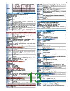
Synchronization frequency range Window wave number
Analysis order
100th order
100th order
80th order
40th order
20th order
10th order
5th order
1
0.5Hz to 40Hz
40Hz to 80Hz
1
2
80Hz to 160Hz
160Hz to 320Hz
320Hz to 640Hz
640Hz to 1.2kHz
1.2kHz to 2.5kHz
2.5kHz to 5.0kHz
4
8
16
32
64
3rd order
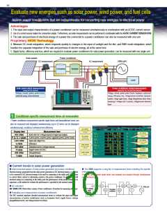
Vector display of electrical angles of motors
Clearly view the inverter efficiency/loss and motor power
3
4
• Display vectors including that of the phase angle and electrical angle
( θ) of fundamental wave voltage and current. The measured data can
be used as parameters to calculate the Ld and Lq values.
• Output, efficiency, and loss of inverter motors can be measured with
one single unit
Operating efficiency and power loss of the inverter and motor can be displayed
when the inputs and outputs of the inverter are measured simultaneously.
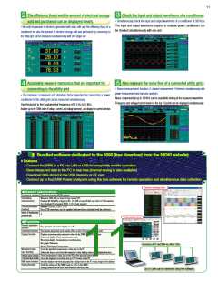
X-Y graph display lets you check the dynamic characteristics of inverters
5
Temperature data that is indispensable for motor evaluation
6
• X-Y graph display function built-in (X-axis: 1 item, Y-axis: 2 items)
By simply setting 2 items to the Y-axis as with a 6-axis graph used to evaluate motors,
you can display the characteristics of a motor and similar devices in real time.
can also be measured simultaneously
• Connect the HIOKI 3440 Series Temperature HiTESTER to measure changes in the motor
temperature and acquire data as parameters for motor evaluation
Connect the HIOKI 3440 Series Temperature HiTESTER to the 3390 (via the
RS-232C interface) to acquire data while displaying the temperature.
To measure temperature, use:
1. HIOKI 3440 Series Temperature HiTESTER
2. Interface Pack 3909
3. RS-232C Cable 9637
Motor
(The same measurements conducted with the HIOKI 3194 can also be performed)
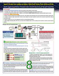
Application 2: Electrical angle measurement using induced voltage of motors
■
Correct the rotation synchronization signal and induced voltage phase of motors as well as measure the phase of voltage and current for the induced voltage of a running motor as
an electrical angle.
Step 1: Turn the motor from the load side, and measure the induced voltage of the motor
Step 2: Measurement of a running motor
○ Measure the fundamental wave’s RMS value
DC power
supply
Torque
sensor
Load/
motor
and the total RMS value of the induced voltage.
Load/
Inverter
Motor
Motor
motor
○ Perform zero compensation for the phase
Induced voltage
between the rotation synchronization signal and
the fundamental wave voltage of the induced
voltage.
Rotation synchronization
signal
Other Advance Functionsmotor
○ Measure the fundamental wave component, harmonic component, and electrical angle of line voltage
and current of a line to the motor. (The measured data can also be used as parameters for calculation of Lp/Lq)
○ Simultaneously measure motor efficiency, inverter efficiency, total efficiency, and inverter loss while
observing the motor control.
• Frequency divider circuit (up to 1/60000 frequency dividing) – helpful when the rotation synchronization
signal consists of multiple pulses for one cycle of induced voltage.
• Δ-to-Y conversation function - convert the line voltage to a phase voltage (virtual neutral reference) when
three-phase three-wire (3P3W3M connection) measurements are performed.

 ASM-SENSOR [ ASM GMBH ]