12
±0.15%f.s. or less (When power factor = 0.0 at 45 Hz to 66 Hz), add
±0.45%f.s. when LPF is 500 Hz
Effect of power
factor
■3390 Specifications
(Accuracy guarantee conditions: 23°C ±3°C, 80%RH or less, warm-up time 30 minutes or more,
sinusoidal wave input, power factor 1, voltage to ground 0 V, in the range where the fundamental
wave meets the conditions of the synchronization source after zero adjustment)
Effective
measurement range
Voltage, current, and power: 1% to 110% of range
Voltage, current, and power: Range’s zero suppress range setting to ±120%
Display range
Input
Selects from OFF, 0.1%f.s., and 0.5%f.s.
* When OFF is selected, a numerical value may be displayed even if zero is input
Zero suppress
range
Single-phase two-wire (1P2W), single-phase three-wire (1P3W), three-
phase three-wire (3P3W2M, 3P3W3M), three-phase four-wire (3P4W)
Measurement line
Voltage: ±10%f.s.
Connection setting
Pattern 1
Pattern 2
Pattern 3
Pattern 4
Pattern 5
Pattern 6
Pattern 7
Pattern 8
CH1
CH2
CH3
CH4
Zero adjustment
Current: ±10%f.s. zero correction is performed for an input offset less than ±4 mV
1P2W
1P2W
1P2W
1P2W
1P2W
1P2W
1P2W
1P2W
Range: Within ±300% of respective voltage and current range
Accuracy: Voltage and current respective display accuracy ±2%f.s.
Waveform peak
measurement
1P3W
3P3W2M
1P3W
1P3W
1P3W
Frequency measurement
3P3W2M
3P3W2M
Number of
measurement channels
4 channels (f1, f2, f3, f4)
3P3W2M
3P3W3M
3P4W
1P2W
1P2W
Measurement
source
Selects from U / I for each input channel
Measurement
method
Measurement
range
Reciprocal method + zero cross sampling value correction
Voltage: 4 channels U1 to U4
Current: 4 channels I1 to I4
Number of input
channels
Within synchronization frequency range between 0.5 Hz and 5 kHz
50 ms (Depends on the frequency when 45 Hz or less )
Voltage: Plug-in terminal (safety terminal)
Current: Dedicated connector
Input terminals
Input method
Data update rate
Voltage: Isolated input, resistance voltage dividing method
Current: Isolated input using current sensor (voltage output)
±0.05%rdg. ±1dgt.
(When sinusoidal waveform is 30% or more relative to the measurement
range of measurement source)
Accuracy
(Selectable for each connection, auto range available)
Measurement range
Voltage range
Current range
15.000V / 30.000V / 60.000V / 150.00V / 300.00V / 600.00V / 1500.0V
0.5000Hz to 9.9999Hz / 9.900Hz to 99.999Hz / 99.00Hz to 999.99Hz /
0.9900kHz to 5.0000kHz
Display range
*400.00mA / *800.00mA / 2.0000A / 4.0000A / 8.0000A / 20.000A (20 A rating)
( ) indicates the 4.0000A / 8.0000A /20.000A / 40.000A / 80.000A / 200.00A (200 A rating)
sensor rating used 1.0000A / 2.0000A / 5.0000A / 10.000A / 20.000A / 50.000A (50 A rating)
10.000A / 20.000A / 50.000A / 100.00A / 200.00A / 500.00A (500 A rating)
Integration measurement
*
Only UNIVERSAL CLAMP ON CT 9277 is applicable
RMS / DC (Selectable for each connection, DC is only available when AC/DC sensor
(6.0000 W to 2.2500 MW)
Depends on combination of voltage and current range
3 (voltage/current), 1.33 for 1500 V
is used for 1P2W connections)
RMS: Integrates the current RMS values and active power values, only the active
values are integrated for each polarity
Power range
Crest factor
Measurement mode
Voltage input part: 2 MΩ ±40 kΩ (Differential input and isolated input)
Current sensor input part: 1 MΩ ±50 kΩ
Input method
(50/60Hz)
DC: Integrates the current values and instantaneous power values for each polarity
Current integration (Ih+, Ih-, Ih), active power integration (WP+, WP-, WP)
Ih+ and Ih- are available only in DC mode, and only Ih is available in RMS mode.
Measurement
item
Measurement
method
Measurement
interval
Display resolution
Measurement
range
Integration time
accuracy
Integration
accuracy
Backup function
Voltage input part: 1500 V ±2000 V peak
Current sensor input part: 5 V ±10 V peak
Maximum input
voltage
Voltage input terminal 1000 V (50/60 Hz)
Digital calculation from each current and active power
Maximum rated
voltage to ground
Measurement category III 600 V (Expected transient overvoltage 6000 V)
Measurement category II 1000 V (Expected transient overvoltage 6000 V)
Data update rate of 50 ms
Voltage and current simultaneous digital sampling and zero cross
synchronization calculation method
Measurement
method
Sampling
Frequency band
Synchronization
frequency range
999999 (6 digits + decimal point)
0 to ±9999.99 TAh / TWh (Integration time is within 9999 h 59 m)
If any integration value or integration time exceeds the above limit, integration stops.
500kHz / 16bit
DC, 0.5 Hz to 150 kHz
±50 ppm ±1 dgt. (0°C to 40°C)
0.5Hz to 5kHz
±(Accuracy of current and active power) ± integration time accuracy
U1 to U4 / I1 to I4 / Ext (with motor analysis option, CH B: when pulse is set) /
DC (50 ms, 100 ms fixed)
* Selectable for each connection (Zero cross auto follow-up by digital LPF when U / 1),
Filter resistance two-stage switching (high / low), source input 30%f.s. or more when U / 1
Synchronization
source
If power fails during integration, integration resumes after power is restored
Harmonic measurement
50ms
Data update rate
LPF
4 channels (Harmonic measurement for another line at a different frequency
OFF / 500 Hz / 5 kHz / 100 kHz (Selectable for each connection)
When 500 Hz: Accuracy +0.1%f.s. specified at 60 Hz or less
When 5 kHz: Accuracy specified at 500 Hz or less
Integration time
accuracy
cannot be performed)
Harmonic voltage RMS value, harmonic voltage percentage, harmonic voltage phase
angle, harmonic current RMS value, harmonic current percentage, harmonic current
phase angle, harmonic active power, harmonic power percentage, harmonic voltage/
current phase difference, total harmonic voltage distortion factor, total harmonic
current distortion factor, voltage disequilibrium factor, current disequilibrium factor
When 100 kHz: Accuracy specified at 20 kHz or less (1%rdg. is added at 10k Hz to 20 kHz)
Measurement item
Polarity
determination
Polarity
determination
Measurement
parameters
Voltage/current zero cross timing comparison method
Voltage (U), current (I), active power (P), apparent power (S), reactive power
(Q), power factor ( λ), phase angle (φ), frequency (f), efficiency (η), loss (Loss),
voltage ripple factor (Ufr), current ripple factor (Ifr), current integration (Ih),
power integration (WP), voltage peak (Upk), current peak (Ipk)
Measurement
method
Zero cross synchronous calculation method (All channels same window) with gap
U1 to U4 / I1 to I4 / Ext (Motor analysis option included, CHB: when pulse is set) /
DC (50 ms/100 ms)
Synchronization
source
FFT processing
word length
Anti-aliasing filter
Accurate
Accuracy
Voltage, currency, and active power measurements
32-bit
Digital filter (Variable by the synchronization frequency)
Rectangular
Voltage (U)
Current (I)
Active power (P)
Window function
±0.1%rdg.±0.1%f.s.
±0.1%rdg.±0.2%f.s.
±0.1%rdg.±0.1%f.s.
±0.05%rdg.±0.05%f.s.
±0.1%rdg.±0.1%f.s.
±0.2%rdg.±0.1%f.s.
±0.3%rdg.±0.2%f.s.
±1.0%rdg.±0.3%f.s.
±20%f.s.
±0.1%rdg.±0.1%f.s.
±0.1%rdg.±0.2%f.s.
±0.1%rdg.±0.1%f.s.
±0.05%rdg.±0.05%f.s.
±0.1%rdg.±0.1%f.s.
±0.2%rdg.±0.1%f.s.
±0.3%rdg.±0.2%f.s.
±1.0%rdg.±0.3%f.s.
±20%f.s.
±0.1%rdg.±0.1%f.s.
±0.1%rdg.±0.2%f.s.
±0.1%rdg.±0.1%f.s.
±0.05%rdg.±0.05%f.s.
±0.1%rdg.±0.1%f.s.
±0.2%rdg.±0.1%f.s.
±0.4%rdg.±0.3%f.s.
±1.5%rdg.±0.5%f.s.
±20%f.s.
DC
Synchronization
frequency range
Data update rate
Phase zero
adjustment
0.5 Hz to 5 kHz
0.5Hz to 30Hz
30Hz to 45Hz
45Hz to 66Hz
66Hz to 1kHz
1kHz to 10kHz
10kHz to 50kHz
50kHz to 100kHz
100kHz to 150kHz
50 ms (Depends on the synchronization frequency when less than 45 Hz)
Phase zero adjustment is possible by key / communication command (only
when the synchronization source is Ext)
Synchronization frequency range Window wave number
Analysis order
100th order
100th order
80th order
40th order
20th order
10th order
5th order
1
1
0.5Hz to 40Hz
40Hz to 80Hz
2
80Hz to 160Hz
160Hz to 320Hz
320Hz to 640Hz
640Hz to 1.2kHz
1.2kHz to 2.5kHz
2.5kHz to 5.0kHz
Maximum
analysis order
4
* Voltage, currency, and active power values at 0.5 Hz to 10 Hz are reference values
* Voltage and active power values more than 220 V at 10 Hz to 16 Hz are reference values
* Voltage and active power values more than 750 V at 30 kHz to 100 kHz are reference values
* Voltage and active power values more than (22000/F [kHz]) V at 100 kHz to 150 kHz are reference values
* Voltage and active power values more than 1000 V are reference values
8
16
32
64
* As for the current and active power values, add the accuracy of the current sensor to the above accuracy
3rd order
Accuracy
guarantee period
Temperature
coefficient
6 months (One-year accuracy is the above accuracy x 1.5)
±0.01%.f.s / °C (When DC: Add ±0.01%f.s./°C)
±0.01%f.s. or less (When applying 1000 V (50/60 Hz) between the voltage
input terminal and the case)
Effect of common
mode voltage
Effect of external
magnetic field
±1.0%f.s. or less (in a magnetic field at 400 A/m, DC, and 50/60 Hz)

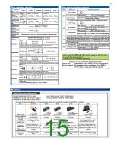
 ASM-SENSOR [ ASM GMBH ]