13
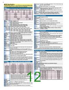
Switchable between Waveform output / Analog output (selects from the
measurement items) * Waveform output is only for CH 1 to CH 8
Frequency
0.5Hz to 30Hz
30Hz to 400Hz
400Hz to 1kHz
1kHz to 5kHz
5kHz to 10kHz
10kHz to 13kHz
Voltage (U) / current (I) / active power(P)
±0.4%rdg.±0.2%f.s.
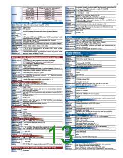
Output content
D-sub 25-pin connector
× 1
Output terminal form
±0.3%rdg.±0.1%f.s.
D/A conversion
resolution
16-bit (Polarity + 15-bit)
±0.4%rdg.±0.2%f.s.
Accuracy
±1.0%rdg.±0.5%f.s.
Analog: DC ±5 Vf.s. (Max. about DC ±12V)
Waveform output: 2 Vrms f.s., crest factor: 2.5 or more
Output voltage
±2.0%rdg.±1.0%f.s.
Analog output: Measurement accuracy ±0.2%f.s. (DC level)
Waveform output: Measurement accuracy ±0.5%f.s. (at RMS level, in
synchronization frequency range)
±5.0%rdg.±1.0%f.s.
Accuracy
* Not specified when the synchronization frequency is 4.3 kHz or more
Noise measurement (FFT processing)
Accuracy
guarantee period
6 months (one-year accuracy is the above accuracy
× 1.5)
1 channel (Selects one channel from CH1 to CH4)
Number of channels
Measurement item
Calculation type
Analog output: 50 ms (As per the data update rate of the selected item)
Waveform output: 500 kHz
Voltage/current
RMS spectrum
Output update rate
100 Ω ±5 Ω
Output resistance
Temperature
coefficient
Measurement
method
FFT processing
word length
500 kHz/s sampling (Decimation after digital anti-aliasing filtering)
32-bit
±0.05%f.s./°C
1,000 points / 5,000 points / 10,000 points / 50,000 points (Linked to the
waveform display record length)
Number of FFT
points
Anti-aliasing filter
Window function
Data update rate
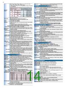
Display
English / Japanese / Chinese (simplified characters)
9-inch TFT color LCD display (800 × 480 pixels)
ON / Auto OFF (1min / 5min / 10min / 30mim / 60min)
99999 counts (Integrated value: 999999 counts)
Display character
Digital filter auto (Variable by the maximum analysis frequency)
Rectangular / Hanning / flat top
Display
LCD backlight
Display resolution
Within about 400 ms to 15 s depending on the number of FFT points, with gap
Maximum analysis
frequency
Frequency
resolution
200 ms (Independent of internal data update rate; waveform and FFT
depend on the screen)
100kHz / 50kHz / 20kHz / 10kHz / 5kHz / 2kHz
Display refresh rate
Display screen
0.2 Hz to 500 Hz (Determined by the number of FFT points and the
maximum analysis frequency)
Measurement, Setting, File Manipulation screens
Calculates the levels and frequencies of voltage and current peaks
(maximum values) for the top 10 points
Noise value
measurement
External interfaces
1. USB Interface (Function)
Series Mini-B receptacle
Connector
Electrical
specification
Number of ports
Class
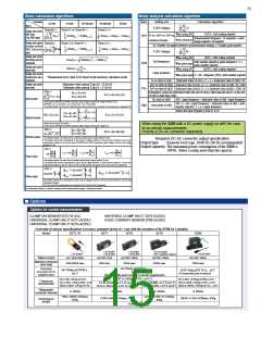
MOTOR TESTING OPTION (Applicable to the 9791 and 9793)
USB2.0 (Full Speed / High Speed)
3 channels
CH A: Analog DC input / frequency input (torque signal input)
CH B: Analog DC input / pulse input (rotation signal input)
CH Z: Pulse input (Z-phase signal input)
Number of input
channels
1
Vendor specific (USB488h)
PC (Windows 2000 / XP / Vista (32-bit version))
Data transfer, remote operation, command control
Destination
Function
Isolation type BNC connector
Input terminal form
Input resistance (DC)
Input method
Measurement item
Maximum input
voltage
1 M Ω ±100 kΩ
2. USB memory interface
Isolated input and differential input (No isolation between CH B and CH Z)
Voltage, torque, rotation, frequency, slip, motor output
USB type A connector
Connector
Electrical
specification
Power supply
USB2.0
±20 V (When analog / frequency / pulse)
Up to 500 mA
1
50 V (50/60 Hz), measurement category I 50 V (Expected transient
overvoltage of 500 V)
Maximum rated
voltage to ground
Number of ports
Applicable USB
memory
Accuracy
guarantee period
USB Mass Storage Class
6 months (One-year accuracy is the accuracy below x 1.5)
Setting file: Save/Load
Measured value/recorded data: Copy (from the CF card data)
Waveform data: Save, screen hard copy
1. Analog DC input (CH A / CH B)
Recordable items
±1 V / ±5 V / ±10 V (When analog DC input )
Measurement range
Effective input range
Sampling
1% to 110%f.s.
10 kHz / 16-bit
3. LAN interface
Connector
Electrical
specification
Transmission
method
Protocol
Function
RJ-45 connector
× 1
Simultaneous digital sampling and zero cross synchronization calculation
method (zero cross averaging)
Measurement
method
IEEE802.3 compliant
Same as the 3390 power measurement input specification (Common for CH A
and CH B)
Synchronization
source
10BASE-T / 100BASE-TX auto recognition
±0.1%rdg. ±0.1%f.s.
Accuracy
TCP/IP
Temperature
coefficient
±0.03%f.s./°C
HTTP server (remote operation), dedicated port (port transfer, command control)
4. CF card interface
±0.01%f.s. or less when applying 50 V (DC 50/60 Hz) between the input
terminal and the 3390 case
Effect of common
mode voltage
TYPE I
× 1
Slot
Compact flash memory card (32 MB or more)
Usable card
Applicable
memory capacity
Data format
Range’s zero suppress range setting to ±120%
Voltage ±10%f.s.
Display range
Zero adjustment
Up to 2 GB
2. Frequency input (only for CH A)
MS-DOS format (FAT16 / FAT32)
Effective
amplitude range
Measurement range
Band width
Accuracy
Display range
±5Vpeak
Setting file: Save / Load
Measured value / automatically recorded data: Save (in CSV format)
Waveform data: Save, screen hard copy
Recordable
items
100kHz
1kHz to 100kHz
±0.05%rdg.±3dgt.
1.000kHz to 99.999kHz
5. RS-232C interface
RS-232C, EIA RS-232D, CCITT V.24, JIS X5101 compliant
Method
Connector
Destination
D-sub 9-pin connector
Printer / thermometer
× 1
3. Pulse input (only for CH B)
Low: 0.5 V or less, High: 2.0 V or more
Detection level
Measurement band
Frequency divider
setting range
Measurement
frequency range
Minimum
detection width
Accuracy
Full duplex asynchronous method
Data length: 8, parity: none, stop bit: 1,
Flow control: Hard flow, delimiter: CR+LF
1 Hz to 200 kHz (When duty ratio is 50%)
Recordable
items
1 to 60000
2400, 9600, 19200, 38400 bps (2400 bps for thermometer)
Baud rate
0.5 Hz to 5.0 kHz (Specified by the frequency at which the measurement
pulse is divided by the set frequency dividing number)
6. Synchronization control interface
IN-side 9-pin round connector ×1, OUT-side 8-pin round connector x 1
Terminal form
Signal
Maximum
allowable input
Signal delay
2.5 μs or more
5 V (CMOS level)
±0.05%rdg. ±3dgt.
±20V
4. Pulse input (only for CH Z)
Up to 2 μs (Specified by the rising edge)
Low: 0.5 V or less, High: 2.0 V or more
Detection level
0.1 Hz to 1 kHz
Measurement band
Functions
1. Setting
Minimum
detection width
2.5 μs or more
rms / mean (Selectable for the voltage/current of each connection)
rms: Displays the true RMS value (True RMS)
mean: Displays the average-value rectified RMS value
OFF / ON (When ON, a frequency divider circuit of CH B is cleared by a rising edge)
Setting
Rectification
switching
D/A OUTPUT OPTION (Applicable to the 9792 and 9793)
OFF / ON (Voltage and current range is selectable for each connection)
Auto range
Number of output
channels
16 channels

 ASM-SENSOR [ ASM GMBH ]