15
Basic calculation algorithms
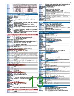
Motor analysis calculation algorithm
Connection
Item
Setting unit
Calculation algorithm
1P2W
1P3W
3P3W2M
3P3W3M
3P4W
M−1
Item
1
A
s
V (DV voltage)
∑
Xrms(i) =
Xrms12 or Xrms34 =
1
Xrms123 =
1
M
s=0
Voltage and current
RMS value
(True RMS value)
M−1
1
When analog DC
When frequency
A [V] × chA scaling setpoint
2
N• m / mN• m / kN• m
common (torque)
chA
X(i)s
Xrms(i) + Xrms(i+1)
Xrms + Xrms + Xrms
)
1 2 3
(
)
(
∑
(
)
)
M s= 0
3
2
(Measurement frequency - fc setpoint) × rated
torque setpoint / fd setpoint
Xmn(i)=
Xmn12 or Xmn34 =
1
Xmn123 =
1
Voltage and current
average rectified
RMS indication
value
M: Number of samples between synchronization timings, s: Sample point number
M−1
π
1
M−1
X
(i)s
Xmn(i) + Xmn(i+1)
Xmn + Xmn + Xmn
)
1 2 3
∑
(
(
1
M
2
2
3
Bs
2
s= 0
V (DC voltage)
∑
s=0
M
Voltage and current
alternating-current
component
When analog DC
B[V] × chB scaling setpoint
2
Xrms(i) 2 − Xdc(i)
)
Xac(i) =
(
)
(
Hz (frequency)
Pole number setpoint x pulse frequency / 2 ×
pulse number setpoint
chB
When pulse inpu
t
M−1
Voltage and current
mean value
1
X(i)s
Xdc(i) = M
∑
s=0
When analog DC
B[V] × chB scaling setpoint
r/min (rotation)
Voltage and current
fundamental wave
component
When pulse inpu
t
2 × 60 × frequency [Hz] / pole number setpoint
Fundamental wave value X1(i) based on the harmonic calculation result
N• m (unit of chA)
(Indicated value of chA )× 2 × π × (indicated value of chB) / 60
Maximum value among X pk+(i) = X (i)s M
Minimum value among X pk-(i) = X (i)s M
Voltage and current
peak value
mN• m (unit of chA) (Indicated value of chA) ×2 × π × (indicated value of chB) / 60 / 1000
kN• m (unit of chA) (Indicated value of chA) ×2 × π × (indicated value of chB) × 1000 / 60
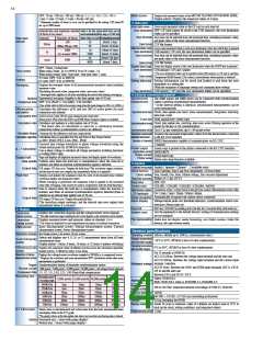
Pm
P(i) =
Calculation cannot be performed when the unit of chA is other than the above, or the unit
of chB is other than r/min.
P12 =P1+P2
M−1
1
P123 =P1+P2+P3
U
(i)s × I(i)s
(
)
∑
P34 =P3+P4
M
s=0
Active power
Hz (unit of chB)
100 × input frequency – indicated value of chB / input frequency
• In the cases of 3P3W3M and 3P4W connections, phase voltage is used for the voltage waveform U (i)s.
(3P3W3M: U1s = (U1s-U3s)/3, U2s = (U2s-U1s)/3, U3s = (U3s-U2s)/3)
• The polarity symbols of active power P indicate the power direction when power is consumed (+P) and when power is regenerated (-P).
100 ×2 × 60 × input frequency – indicated value of chB × pole
number setpoint / 2 × π × input frequency
r/min (unit of chB)
Slip
3
Selects the input frequency from f1 to f4
S12
S34
=
=
S +S
(
1 2
)
)
S12 =S1+S2
S34 =S3+S4
2
3
S(i) =U(i)5I(i)
S123 =S1+S2+S3
Apparent power
S3 +S4
(
2
• Selects rms or mn for U(i) and I(i)
• In the cases of 3P3W3M and 3P4W connections, phase voltage is used for the voltage U (i)
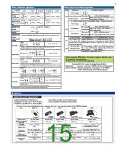
When using the 3390 with a DC power supply as with the case
of on-vehicle measurements:
Provide a DC-AC converter separately.
Q(i) =
Q12 =Q1+Q2
Q34 =Q3+Q2
Q123 =Q1+Q2+Q3
2
si(i)
S
(i)2 − P(i)
Reactive power
Power factor
• The polarity symbol si of reactive power Q indicates symbol [none]: lag and symbol [-]: lead.
• The polarity symbol si(i) is determined by lag or lead of voltage waveform U (i)s and current waveform I (i)s for each
measurement channel (i), and in the cases of 3P3W3M and 3P4W connections, phase voltage is used for the voltage
waveform U (i)s.
Required DC-AC converter output specification
Output type
: Sinusoid wave type, 50/60 Hz (60 Hz recommended)
Output capacity: The maximum power consumption of the 3390 is
λ(i) =
140VA. Select a rating more than the capacity.
P
P34
P
123
12
P
(i)
λ12 = si12
λ34= si34
λ123 = si123
,
si
(i) S(i)
S
S
S
12
34
123
• The polarity symbol si of power factor λ indicates symbol [none]: lag and symbol [-]: lead.
• The polarity symbol si(i) is determined by lead or lag of voltage waveform U (i)s and current waveform I (i)s for each
measurement channel (i), and si12, si34, and si123 are determined by the symbol of Q12, Q34, and Q123, respectively.
φ12 = si12cos−1 λ12
φ34 = si34cos−1 λ34
φ(i) =
si(i)cos−1
φ123 = si123cos−1 λ123
λ
(i)
Phase angle
The polarity symbol si(i) is determined by lead or lag of voltage waveform U (i)s and current waveform I (i)s for each
measurement channel.
si12, si34, and si123 are determined by the symbol of Q12, Q34, and Q123, respectively.
(i): Measurement channel, M: Number of samples between synchronization timings, s: Sample point number
Options
■
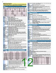
Options for current measurements
CLAMP ON SENSOR 9272-10 (AC)
UNIVERSAL CLAMP ON CT 9277 (AC/DC)
UNIVERSAL CLAMP ON CT 9278 (AC/DC)
UNIVERSAL CLAMP ON CT 9279 (AC/DC)
AC/DC CURRENT SENSOR 9709 (AC/DC)
Overview of sensor specifications (Accuracy guarantee period of 1 year with the exception of the 9709 for 6 months)
Model
9272-10
9277
9278
9279
9709
CAT II 600V
CAT III 300V
CAT II 600V
CAT III 300V
Not CE-marked
600 V insulated conductor
CAT III 600V
CAT III 1000V
AC 20A/200A
AC/DC 20A
50A rms
AC/DC 200A
AC/DC 500A
650A rms
AC/DC 500A
700A rms
Rated current
Maximum continuous
input range
50A/300A rms
350A rms
±0.5%rdg.±0.05%f.s. ,
±0.2°
(30 minutes after power is turned on and after magnetization)
Accuracy
(45 to 66 Hz, DC: DC
compatible sensor)
±0.3%rdg.±0.01%f.s.,
±0.2°
±0.05 %rdg.±0.01 % f.s. , ±0.2°
(10 minutes after power is turned on)
DC to 1kHz: ±1.0% ( ±0.5°)
1Hz to 5Hz: ±2%rdg.±0.1%f.s.
1kHz to 5kHz: ±1%rdg.±0.05%f.s. (±1.0)°
10kHz to 50kHz: ±5%rdg.±0.1%f.s.
DC to 45Hz: ±0.2%rdg.±0.02%f.s.(±0.3°)
5kHz to 10kHz: ±2%rdg.±0.1%f.s. (±2.0°)
20kHz to 100kHz: ±30%rdg.±0.1%f.s. (±30°)
Frequency
characteristic
1 k to 50 kHz: ±2.5 % (±2.5°)
50 k to 100 kHz: ±5.0 % (±5.0°)
1 k to 10 kHz: ±2.5 % (±2.5°)
10 k to 20 kHz: ±5.0 % (±5.0°)
Measurable
conductor diameter
φ 46mm
φ 20mm
φ 40mm
φ 36mm
78W×188H×35Dmm,
850g
220W×103H×43.5Dmm,
860g
176W×69H×27Dmm, 470g
160W×112H×50Dmm, 850g
Dimensions/
weight
Cord length: 3 m

 ASM-SENSOR [ ASM GMBH ]