14
OFF / 50 ms / 100 ms / 200 ms / 500 ms / 1 s / 5 s / 10 s / 15 s / 30 s /
1 min / 5 min / 10 min / 15 min / 30 min / 60 min
* Maximum number of items to save can be specified by the setting (130 items/50
ms, up to 5000 items)
Displays the measured values of the
Display pattern: Displays the numerical values of 4 items
(
).
Motor screen
MOTOR TESTING OPTION 9791 9793
3. Data save
Auto data save
Saves each measured value to the CF card at each interval
Save destination OFF / CF card (cannot be saved to the USB memory), the save destination
Interval time and maximum number Guide to the time during which items can be
folder can be specified
of Items to be saved
saved automatically(When using a 512 MB card)
Save itemAuto
Any item can be selected from all measured data, including harmonic value,
and peak value of the noise measurement function
Interval
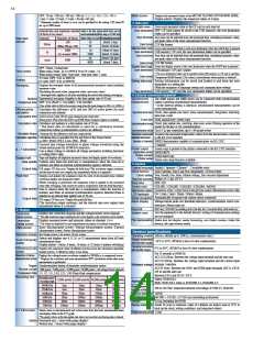
Number of items Number of items to be saved Time during which items can be stored
Data save
interval
130
10
40
About 2 days
About 14 hours
About 42 days
About 11 hours
About 416 days
About 7 days
50ms
Data format
CSV file format
(When 200 ms: 520)
2600
Saves each measured value to each save destination when the SAVE key is pressed
Manual data Save
10
Save destination USB memory / CF card, the save destination folder can be specified
Save itemSave
1s
(5 s or more: 5000)
1000
40
Any item can be selected from all measured data, including harmonic value,
and peak value of the noise measurement function
5000
1min
4000
CSV file format
Data format
Saves the display screen to the save destination when the COPY key is pressed
Screen hard copy
Save destination
OFF / Timer / Actual time
When using Timer: 10 s to 9999 h 59 m 59 s (unit: 1 s)
When using Actual Time: Start time / stop time (unit: 1 min)
USB memory / CF card / printer
* The save destination folder can be specified when USB memory or CF card is specified.
Time control
Data format
Compressed BMP format (256 colors), monochrome when printer is selected
VT ratio: OFF / 0.01 to 9999.99
CT ratio: OFF / 0.01 to 9999.99
Scaling
Setting information can be saved and loaded to and from the save
destination as a setting file
(With the exception of language setting and communication setting)
Setting data save
Displays the averaged values of all instantaneously measured values including
harmonic value
Averaging
Save destination USB memory / CF card (the save destination folder can be specified)
(Excluding the peak value, integrated value, and noise value)
* Averaged data applies to all data including the saved data during averaging
4. External connected equipment
Exponential averaging (Applies to the data update rate of 50 ms)
Method
Response time
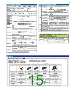
The
master and
slaves can be connected with synchronization
3390
Synchronized
measurement
3390
cables to perform synchronized measurements
* If the interval setting is identical, synchronized measurements can be
saved automatically
OFF / 0.2s (FAST) / 1.0s (MID) / 5.0s (SLOW)
(Time within which to fall in the accuracy range when the input changes to 0%f.s. to 100%f.s.)
Calculates the efficiency η[%] and loss [W] of active power for each
connection and channel.
Efficiency/loss
calculation
Calculated item
Synchronized item Clock, data update rate (excl. noise measurement), integration start/stop,
data reset, event
Active power value (P) for each channel and connection
Event item
Motor power (Pm) when the
and
Motor Analysis Option is included
9793
9791
Hold, manual save, screen copy
Calculates and updates at a data update rate of 50 ms
* The latest data of calculation is used for a calculation between
connections whose synchronization sources are different
Calculation rate
Clock, data update rate, start/stop, data reset, event (During operation of the
master by the key or via communication)
Synchronization timing
Synchronization delay Up to 5 μs per connection, up to +50 ms per event
3 formats for the efficiency and loss, respectively
Calculable factors
Calculation algorithm
Acquires the measured temperature values from the thermometer connected
to the RS-232C interface
Temperature measurement
Applicable thermometer
Calculated item is specified for Pin and Pout in the format below
=100 Pout / Pin , Loss= Pin - Pout
h
5
Number of channels HIOKI thermometers capable of communication via RS-232C
Converts line voltage waveform to phase voltage waveform using the
virtual neutral point for 3P3W3M connection
Uses a phase voltage to calculate all voltage parameters including harmonic
or voltage RMS value
1 channel
Screen copy is printed to the printer connected to the RS-232C interface
Printer output
Applicable printer
Output content
Printer setup
Δ – Y calculation
HIOKI
9670
Screen hard copy
Stops and displays all displayed measured values and display update of waveforms
Display hold
Data update
Printer auto setup function available
Updates data when the hold key is manipulated, when the interval is
reached, and when an external synchronization signal is detected
5. System
English / Japanese / Chinese* (*available soon)
Display language
Clock function
Clock setting
D/A output, CF data save: Outputs the hold data (The waveform output continues,
and the interval auto-save outputs data immediately before it is updated )
Output data
Peak hold
Auto Calendar, Auto Leap Year Adjustment, 24 Hour Meter
Year, Month, Day, Hour, Minute Setting, Zero Second Adjustment
Displays and updates the maximum value for each of all measured data (without
waveform display and integrated value)
Real time accuracy Within ±3 s / day (25°C)
(While averaging is performed, the maximum value is applied to the measured
value after averaging. This cannot be used in conjunction with the Hold function)
OFF / ON
Beep tone
Screen color
Start screen select
LCD backlight
Sensor recognition
Alarm display
COLOR1 / COLOR2 / COLOR3 / COLOR4 / MONO
Connection screen / screen closed in the previous session (Measurement screen only)
ON / 1min / 5min / 10min / 30min / 60min
Data update
Output data
Data is cleared when the hold key is manipulated, when the interval is
reached, and when an external synchronization signal is detected (Data is
updated at an internal data update rate of 50 ms)
Automatically recognizes the current sensor connected
Voltage/current peak over threshold detection, synchronization source non-
detection (Alarm mark on)
D/A output, CF data save: Outputs the peak hold data
(The waveform output continues, and the interval auto-save outputs data
immediately before it is cleared)
ESC key: ON/OFF by holding down the key for 3 seconds (Key lock mark on)
Sets the equipment to the default (factory) settings (Communication settings
are not changed)
Key lock
System reset
2. Display
Connection
check screen
Displays the connection diagram and the voltage/current vector diagram
* The right connection range is displayed in the vector diagram, so the connection can be checked.
Media data list display, media formatting, new folder creation, folder file
deletion, file copy between media
File manipulation
Displays measured power and harmonic values on channels 1 to 4
* The values are displayed for each measurement line pattern of combined connections
Connection
display screen
Basic Measurement screen, Voltage Measurement screen, Current
Measurement screen, Power Measurement screen
DMM screen
General specifications
Bar Graph screen, List screen, Vector screen
Harmonic screen
Indoors, altitude up to 2000 m, contamination class 2
Operating location
Selects and displays any 4, 8, 16, or 32 measurement items from all basic
measurement items
Display pattern: 4 items, 8 items, 16 items, or 32 items (4 pattern switching)
Storage temperature
and humidity ranges
Select/Display
screen
-10°C to 50°C, 80%RH or less (No dew condensation)
0°C to 40°C, 80%RH or less (No dew condensation)
Operating temperature
and humidity ranges
Displays the numerical values of efficient and loss set in the calculation algorithm
Display pattern: 3 efficiency items, 3 loss items.
Efficiency/Loss
screen
For 15 seconds at 50/60 Hz
Displays the voltage/current waveforms sampled at 500 kHz in a compressed screen
* Displays the waveform and noise measurement (FFT calculation) result when noise
measurement is performed
Waveform & Noise
Measurement screen
AC5.312 kVrms: Between the voltage input terminal and the unit case
AC3.32 kVrms: Between the voltage input terminal and the current input
terminal / interface
Withstand voltage
Trigger Synchronization timing of harmonic synchronization source
AC370 Vrms: Between the
CH Z) and the unit case
and
input terminals (CH A, CH B,
9793
9791
Record Length
Compression Ratio
Recording time
1,000 points / 5,000 points / 10,000 points / 50,000 points × all voltage/current channels
1/1, 1/2, 1/5, 1/10, 1/25, 1/50 (Peak-Peak compression)
Between CH A and CH B / CH Z
Safety: EN61010-1
Recording speed /
Recording length
1,000 points 5,000 points 10,000 points 50,000 points
Applicable standard
EMC: EN61326-1 Class A, EN61000-3-2, EN61000-3-3
2ms
4ms
10ms
20ms
20ms
40ms
100ms
200ms
500kS/s
250kS/s
100kS/s
50kS/s
25kS/s
10kS/s
Rated power
supply voltage
Maximum rated power
Dimensions
Weight
100 to 240 VAC (expected transient overvoltage of 2500 V), 50/60 Hz
10ms
20ms
40ms
100ms
50ms
100ms
200ms
400ms
1000ms
500ms
140VA
340 (W) × 170 (H) ×157 (D) mm (excluding protrusions)
100ms
200ms
500ms
1000ms
2000ms
5000ms
4.8 kg (including the
)
9793
About 10 years (a reference value of a lithium ion battery used at 23°C to
back up the clock, setting conditions, and integrated values)
1 year
Backup battery life
Selects items on the horizontal and vertical axes from the basic measurement items
and displays them in the X-Y graph
X-Y Plot screen
Product warranty period
*The graph is drawn at the data update rate, data is not recorded, and drawing data is cleared
Option Horizontal axis: 1 item (with gauge display)
Vertical axis: 2 items (with gauge display)

 ASM-SENSOR [ ASM GMBH ]