AX88179
USB 3.0 to 10/100/1000M Gigabit Ethernet Controller
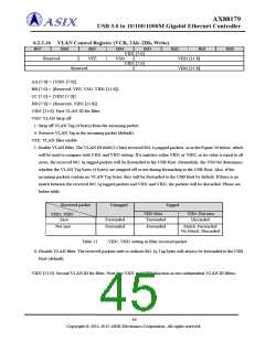
6.2.2.16 VLAN Control Register (VCR, 2Ah~2Dh, Write)
Bit7
Bit6
Bit5
Bit4
Bit3
VID1 [7:0]
Bit2
VID1 [11:8]
VID2 [11:8]
Bit1
Bit0
Reserved
VFE
VSO
VID2 [7:0]
Reserved
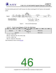
AA [7:0] = {VID1 [7:0]}.
BB [7:0] = {Reserved, VFE, VSO, VID1 [11:8]}.
CC [7:0] = {VID2 [7:0]}.
DD [7:0] = {Reserved, VID2 [11:8]}.
VID1 [11:0]: First VLAN ID for filter.
VSO: VLAN Strip off
1: Strip off VLAN Tag (4 bytes) from the incoming packet.
0: Preserve VLAN Tag in the incoming packet (default).
VFE: VLAN filter enable
1: Enable VLAN filter. The VLAN ID field (12 bits) received 802.1q tagged packets, as in the Figure 26 below, which
will be used to compare with VID1 and VID2 setting. If it matches either VID1 or VID2, or its value is equal to all
zeros, the received 802.1q tagged packets will be forwarded to the USB Host. Meanwhile, the VSO bit determines
whether the VLAN Tag bytes (4 bytes) are stripped off or not during forwarding to the USB Host. Also, if the
incoming packets contain no VLAN Tag bytes, they will be forwarded to the USB Host by default. If there is no
match between the received 802.1q tagged packets and VID1 and VID2, the packets will be discarded. Please see
below table.
Received packet
VID1, VID2
Untagged
Tagged
VID=Zero
Forwarded
VID= Not zero
Discarded
Zero
Forwarded
Forwarded
Not zero
Forwarded
Match: Forwarded
No Match: Discarded
Table 11
: VID1, VID2 setting to filter received packet
0: Disable VLAN filter. The received packets with or without 802.1q Tag bytes will always be forwarded to the USB
Host (default).
VID2 [11:0]: Second VLAN ID for filter. Note that VID1 and VID2 function as two independent VLAN ID filters.
44
Copyright © 2011-2012 ASIX Electronics Corporation. All rights reserved.

 ASIX [ ASIX ELECTRONICS CORPORATION ]