AX88179
USB 3.0 to 10/100/1000M Gigabit Ethernet Controller
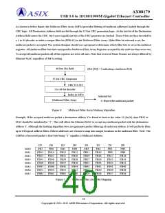
As shown in below figure, the Multicast Filter Array (MFA) provides filtering of multicast addresses hashed through the
CRC logic. All Destination Address field are fed through the 32 bits CRC generation logic. As the last bit of the Destination
Address field enters the CRC, the 6 most significant bits of the CRC generator are latched. These 6 bits are then decoded by
a 1 to 64 decoder to index a unique filter bit (FB0-63) in the Multicast Filter Array. If the filter bit selected is set, the
multicast packet is accepted. The system designer should use a program to determine which filter bits to set in the multicast
registers. All multicast filter bits that correspond to Multicast Filter Array Registers accepted by the node are then set to one.
To accept all multicast packets all of the registers are set to all ones. Note that received Pause Frames are always filtered by
Ethernet MAC regardless of MFA setting.
48 bits DA field
(DA [40] = 1 indicating a multicast DA)
32-bit CRC Generator
CRC [31:26]
1 to 64-bit decoder
Index to MFA
Multicast Filter Array
Selected bit:
0: Reject the multicast packet
Figure 6
: Multicast Filter Array Hashing Algorithm
Example: If the accepted multicast packet’s destination address Y is found to hash to the value 32 (0x20), then FB32 in
MA4 should be initialized to “1”. This will allow the Ethernet MAC to accept any multicast packet with the destination
address Y. Although the hashing algorithm does not guarantee perfect filtering of multicast address, it will perfectly filter
up to 64 logical address filters if these addresses are chosen to map into unique locations in the multicast filter. Note: The
LSB bit of received packet’s first byte being “1” signifies a Multicast Address.
D7
D6
D5
D4
D3
D2
D1
D0
MA0
MA1
MA2
MA3
MA4
MA5
MA6
MA7
FB7
FB6
FB5
FB4
FB3
FB2
FB1
FB0
FB15
FB23
FB31
FB39
FB47
FB55
FB63
FB14
FB22
FB30
FB38
FB46
FB54
FB62
FB13
FB21
FB29
FB37
FB45
FB53
FB61
FB12
FB20
FB28
FB36
FB44
FB52
FB60
FB11
FB19
FB27
FB35
FB43
FB51
FB59
FB10
FB18
FB26
FB34
FB42
FB50
FB58
FB9
FB8
FB17
FB25
FB33
FB41
FB49
FB57
FB16
FB24
FB32
FB40
FB48
FB56
Figure 7
: Multicast Filter Array Bit Mapping
39
Copyright © 2011-2012 ASIX Electronics Corporation. All rights reserved.

 ASIX [ ASIX ELECTRONICS CORPORATION ]