APW8713
Function Description
Constant-On-Time PWM Controller with Input Feed-
Forward
Where FSW is the nominal switching frequency of the
converter in PWM mode.
The constant on-time control architecture is a pseudo-
fixed frequency with input voltage feed-forward. This ar-
chitecture relies on the output filter capacitor’s effective
series resistance (ESR) to act as a current-sense resistor,
so the output ripple voltage provides the PWM ramp signal.
In PFM operation, the high-side switch on-time controlled
by the on-time generator is determined solely by a one-
shot whose pulse width is inversely proportional to input
voltage and directly proportional to output voltage. In PWM
operation, the high-side switch on-time is determined by
a switching frequency control circuit in the on-time gen-
erator block.
The load current at handoff from PFM to PWM mode is
given by:
1
2
VIN - VOUT
ILOAD (PFM toPWM)
=
´
´ TON-PFM
L
V
IN - VOUT
1
VOUT
=
´
´
2L
FSW
V
IN
Forced-PWM Mode
The Forced-PWM mode disables the zero-crossing
comparator, which truncates the low-side switch on-time
at the inductor current zero crossing. This causes the
low-side gate-drive waveform to become the complement
of the high-side gate-drive waveform. This in turn causes
the inductor current to reverse at light loads while UG
maintains a duty factor of VOUT/VIN. The benefit of Forced-
PWM mode is to keep the switching frequency fairly
constant. The Forced-PWM mode is most useful for re-
ducing audio frequency noise, improving load-transient
response, and providing sink-current capability for dy-
namic output voltage adjustment.
The switching frequency control circuit senses the switch-
ing frequency of the high-side switch and keeps regulat-
ing it at a constant frequency in PWM mode. The design
improves the frequency variation and is more outstand-
ing than a conventional constant on-time controller, which
has large switching frequency variation over input voltage,
output current and temperature. Both in PFM and PWM,
the on-time generator, which senses input voltage on
VIN pin, provides very fast on-time response to input line
transients.
When VPFM is above the PFM high threshold (2.5V,
minimum), the converter is in forced-PWM mode. When
VPFM is below the PFM low threshold (0.5V, maximum),
the chip is in automatic PFM/PWM Mode.
Another one-shot sets a minimum off-time (typical:
250ns). The on-time one-shot is triggered if the error com-
parator is high, the low-side switch current is below the
current-limit threshold, and the minimum off-time one-
shot has timed out.
Power-On-Reset
A Power-On-Reset (POR) function is designed to prevent
wrong logic controls when the VCC voltage is low. The
POR function continually monitors the bias supply volt-
age on the VCC pin if at least one of the enable pins is set
high. When the rising VCC voltage reaches the rising
POR voltage threshold (4.35V, typical), the POR signal
goes high and the chip initiates soft-start operations.
Should this voltage drop lower than 4.25V (typical), the
POR disables the chip.
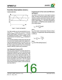
Over-Current Protection of the PWM Converter
In PFM mode, an automatic switchover to pulse-frequency
modulation (PFM) takes place at light loads. This
switchover is affected by a comparator that truncates the
low-side switch on-time at the inductor current zero
crossing. This mechanism causes the threshold between
PFM and PWM operation to coincide with the boundary
between continuous and discontinuous inductor-current
operation (also known as the critical conduction point).
The on-time of PFM is given by:
En Pin Control
When VEN is above the EN high threshold (2.5V,
minimum), the converter is enabled. When VEN is below
the EN low threshold (0.5V, maximum), the chip is in the
shutdown and only low leakage current is taken from
VCC.
1
VOUT
TON-PFM
=
´
FSW
V
IN
Copyright ã ANPEC Electronics Corp.
14
www.anpec.com.tw
Rev. A.3 - Sep., 2013

 ANPEC [ ANPEC ELECTRONICS COROPRATION ]