APW8713
Function Description (Cont.)
Programming the On-Time Control and PWM Switch-
ing Frequency
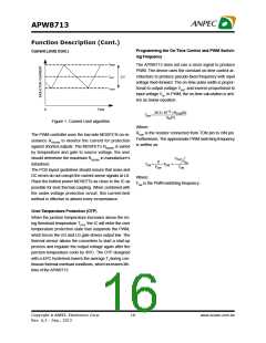
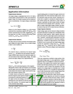
Current Limit( Cont.)
IPEAK
The APW8713 does not use a clock signal to produce
PWM. The device uses the constant on-time control ar-
chitecture to produce pseudo-fixed frequency with input
voltage feed-forward. The on-time pulse width is propor-
tional to output voltage VOUT and inverse proportional to
input voltage VIN. In PWM, the on-time calculation is writ-
ten as below equation.
IOUT
ΔI
ILIMIT
0
Time
26.3´ 10-12 ´ RTON(W)
TON
=
V (V)
IN
Figure 1. Current Limit algorithm
Where:
RTON is the resistor connected from TON pin to VIN pin.
Furthermore, The approximate PWM switching frequency
is written as:
The PWM controller uses the low-side MOSFETs on-re-
sistance RDS(ON) to monitor the current for protection
against shorted outputs. The MOSFET’s RDS(ON) is varied
by temperature and gate to source voltage, the user
should determine the maximum RDS(ON) in manufacture’s
datasheet.
VOUT
D
V
IN
TON
=
,FSW =
FSW
TON
The PCB layout guidelines should ensure that noise and
DC errors do not corrupt the current-sense signals at LX.
Place the hottest power MOSEFTs as close to the IC as
possible for best thermal coupling. When combined with
the under-voltage protection circuit, this current-limit
method is effective in almost every circumstance.
Where:
FSW is the PWM switching frequency.
Over-Temperature Protection (OTP)
When the junction temperature increases above the ris-
ing threshold temperature TOTR, the IC will enter the over
temperature protection state that suspends the PWM,
which forces the UG and LG gate drivers output low. The
thermal sensor allows the converters to start a start-up
process and regulate the output voltage again after the
junction temperature cools by 45oC. The OTP designed
with a 45oC hysteresis lowers the average TJ during con-
tinuous thermal overload conditions, which increases life-
time of the APW8713.
Copyright ã ANPEC Electronics Corp.
16
www.anpec.com.tw
Rev. A.3 - Sep., 2013

 ANPEC [ ANPEC ELECTRONICS COROPRATION ]