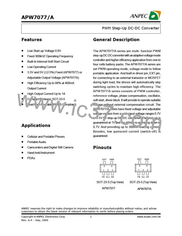
APW7077/A
Function Description (Cont.)
The inductor peak current can be calculated as
Step–up Converter Operating Mode (Cont.)
VOUT ´ IO
DIL
givenby
Ipk =
+
V OUT - V IN
VIN
2
D =
V OUT
NOTES:
D – On–time duty cycle
In higher output voltage or small output current
application, the step–upDC–DC controller operated in
IL – Average inductor current
discontinuous conduction mode almost. For a step-up
converter in a DCM, the duty cycle D is given by
IPK – Peak inductor current
IO – Desired dc output current
VIN – Nominal operating dc input voltage
VOUT – Desired dc output voltage
ESR – Equivalent series resistance of the output
æ
ö
V
V
2×L
T ×R
OUT
OUT
ç
ç
è
÷
- 1
D =
×
÷
V
V
IN
S
LOAD
IN
ø
External components values can be calculated from
these equations, however, theoptimized value should
obtained through experimental results.
capacitor
Inductor Selection
Critical Inductance Value
APW7077/A series are designed to work well with a
6.8 to 12uH inductors in most applications 10uH is a
sufficiently low value to allow the use of a small
surface mount coil, but large enough to maintain low
ripple. Lower inductance values supply higher output
current, but also increase the ripple and reduce
efficiency. Higher inductor values reduce ripple and
improve efficiency, but also limit output current. The
inductor should have small DCR, usually less than
1mW, to minimize loss. It is necessary to choose an
inductor witha saturation current greater than thepeak
current which the inductor will encounter in the
application.
The minimum value of inductor to maintain continuous
conduction mode can be determined by the following
equation.
VOUT ´ D(1- D)2
L ³
fsw ´ IO ´ Ratio
A system can be designed to operate in continuous
mode for load currents above a certain level usually
20 to 50% (Ratio define as 0.2~0.5) of full load at
minimum inputvoltage.WhenIO smallerthan(IO*Ratio),
the controller system will into DCM.
DIL is the ripple current flowing through the inductor,
whichaffectsthe output voltageripple and corelosses.
Based on 20%(Ratio=0.2) current ripple, VOUT=5V,
IO=1A and VIN =1.8V system, the inductance value is
calculated as 6.9uH and a 6.8uH inductor is used.
The inductor ripple current is important for a few
reasons. One reason is because the peak switch
current will be the average inductor current (IL) plus
DIL.
The inductor current ripple has an expression
As a side note, discontinuous operation occurs when
the inductor current falls to zero during a switching
cycle, or DIL is greater than the average inductor
current.Therefore, continuousconductionmodeoccurs
VIN ´ D
DIL =
fsw ´ L
The maximum DC input current can be calculated as
VOUT ´ IO(max)
IL(max) =
VIN (min)
Copyright ã ANPEC Electronics Corp.
13
www.anpec.com.tw
Rev. A.4 - Sep, 2005

 ANPEC [ ANPEC ELECTRONICS COROPRATION ]