APA2030/2031
Application Descriptions
Power supply decoupling also prevents the oscilla-
tions causing by long lead length between the ampli-
fier and the speaker.
Optimizing Depop Circuitry
Circuitry has been included in the APA2030/1 to mini-
mize the amount of popping noise at power-up and
when coming out of shutdown mode. Popping occurs
whenever a voltage step is applied to the speaker. In
order to eliminate clicks and pops, all capacitors must
be fully discharged before turn-on. Rapid on/off
switching of the device or the shutdown function will
cause the click and pop circuitry. The value of Ci will
also affect turn-on pops. (Refer to Effective Bypass
Capacitance) The bypass voltage rise up should be
slower than input bias voltage. Although the bypass
pin current source cannot be modified, the size of
Cb can be changed to alter the device turn-on time
and the amount of clicks and pops. By increasing the
value of Cb, turn-on pop can be reduced. However,
the tradeoff for using a larger bypass capacitor is to
increase the turn-on time for this device. There is a
linear relationship between the size of Cb and the
turn-on time.
The optimum decoupling is achieved by using two dif-
ferent type capacitors that target on different type of
noise on the power supply leads. For higher frequency
transients, spikes, or digital hash on the line, a good
low equivalent-series-resistance(ESR) ceramic
capacitor, typically 0.1µF placed as close as possible
to the device VDD lead works best. For filtering lower-
frequency noise signals, a large aluminum electrolytic
capacitor of 10µF or greater placed near the audio
power amplifier is recommended.
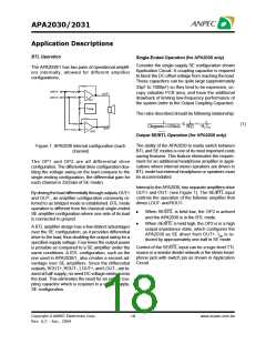
Shutdown Function
In order to reduce power consumption while not in use,
the APA2030/1 contains a shutdown pin to externally
turn off the amplifier bias circuitry. This shutdown fea-
ture turns the amplifier off when a logic low is placed
on the SHUTDOWN pin. The trigger point between a
logic high and logic low level is typically 2.0V. It is
best to switch between ground and the supply VDD to
provide maximum device performance.
In a SE(for APA2030) configuration, the output cou-
pling capacitor, CC, is of particular concern. This ca-
pacitor discharges through the internal 10kΩ resistors.
Depending on the size of CC, the time constant can
be relatively large. To reduce transients in SE mode,
an external 1kΩ resistor can be placed in parallel
with the internal 10kΩ resistor. The tradeoff for using
this resistor is an increase in quiescent current.
By switching the SHUTDOWN pin to low, the amplifier
enters a low-current state, IDD<50µA. APA2030 is in
shutdown mode, except PC-BEEP detect circuit. On
normal operating, SHUTDOWN pin pull to high level to
keeping the IC out of the shutdown mode. The SHUT-
DOWN pin should be tied to a definite voltage to avoid
unwanted state changes.
In the most cases, choosing a small value of Ci in the
range of 0.33µF to 1µF, Cb being equal to 0.47µF and
an external 1kΩ resistor should be placed in parallel
with the internal 10kΩ resistor should produce a virtu-
ally clickless and popless turn-on.
PC-BEEP Detection ( for APA2030 only)
APA2030 integrates a PCBEEP detect circuit for
NOTEBOOK PC used. When PC-BEEP signal drive
to PCBEEP input pin, and PCBEEP mode is active.
APA2030 will force to BTL mode and the internal gain
fixed as -10dB. The PCBEEP signal becomes the
amplifier input signal and play on the speaker without
coupling capacitor. If the amplifier in the shutdown
mode, it will out of shutdown mode whenever PCBEEP
mode enable. The APA2030 will return to previous
setting when it is out of PC-BEEP mode.
A high gain amplifier intensifies the problem as the
small delta in voltage is multiplied by the gain. So it
is advantageous to use low-gain configurations.
BTL Amplifier Efficiency
An easy-to-use equation to calculate efficiency starts
out as being equal to the ratio of power from the power
supply to the power delivered to the load. The follow-
ing equations are the basis for calculating amplifier
efficiency.
The input impedance is 100kΩ on PCBEEP input
pin.
Copyright ANPEC Electronics Corp.
21
www.anpec.com.tw
Rev. A.2 - Apr., 2004

 ANPEC [ ANPEC ELECTRONICS COROPRATION ]