APA2030/2031
Application Descriptions
BTL Operation
Single-Ended Operation (for APA2030 only)
Consider the single-supply SE configuration shown
Application Circuit. A coupling capacitor is required
to block the DC offset voltage from reaching the load.
These capacitors can be quite large (approximately
The APA2030/1 has two pairs of operational amplifi-
ers internally, allowed for different amplifier
configurations.
33µF to 1000µF) so they tend to be expensive, oc-
cupy valuable PCB area, and have the additional
drawback of limiting low-frequency performance of
the system (refer to the Output Coupling Capacitor).
-
+
INPUT-
OUT+
INPUT+
OP1
Vbias
The rules described should be following relationship:
-
+
1
1
1
≤
RiCi <<
(1)
DI F F _AM P _C ONF I G
Cbypass ×125kΩ
RLCC
OUT-
OP2
Output SE/BTL Operation (for APA2030 only)
The ability of the APA2030 to easily switch between
BTL and SE modes is one of its most important costs
saving features. This feature eliminates the require-
ment for an additional headphone amplifier in appli-
cations where internal stereo speakers are driven in
BTL mode but external headphone or speakers must
be accommodated.
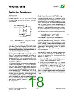
Figure 1: APA2030 internal configuration (each
channel)
The OP1 and OP2 are all differential drive
configuration, The differential drive configuration dou-
bling the voltage swing on the load compare to the
single-ending configuration, the differential gain for
each channel is 2X(Gain of SE mode).
Internal to the APA2030, two separate amplifiers drive
OUT+ and OUT- (see Figure 1). The SE/BTL input
controls the operation of the follower amplifier that
drives LOUT- and ROUT-.
By driving the load differentially through outputs OUT+
and OUT-, an amplifier configuration commonly re-
ferred to as bridged mode is established. BTL mode
operation is different from the classical single-ended
SE amplifier configuration where one side of its load
is connected to ground.
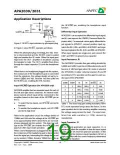
•
When SE/BTL is held low, the OP2 is actived
and the APA2030 is in the BTL mode.
When SE/BTL is held high, the OP2 is in a high
output impedance state, which configures the
APA2030 as SE driver from OUT+. I is re-
duced by approximately one-half in SEDmD ode.
•
A BTL amplifier design has a few distinct advantages
over the SE configuration, as it provides differential
drive to the load, thus doubling the output swing for a
specified supply voltage. Four times the output power
is possible as compared to a SE amplifier under the
same conditions. A BTL configuration, such as the
one used in APA2030/1, also creates a second ad-
vantage over SE amplifiers. Since the differential
outputs, ROUT+, ROUT-, LOUT+, and LOUT-, are bi-
ased at half-supply, no need DC voltage exists across
the load. This eliminates the need for an output cou-
pling capacitor which is required in a single supply,
SE configuration.
Control of the SE/BTL input can be a logic-level TTL
source or a resistor divider network or the stereo head-
phone jack with switch pin as shown in Application
Circuit.
Copyright ANPEC Electronics Corp.
18
www.anpec.com.tw
Rev. A.2 - Apr., 2004

 ANPEC [ ANPEC ELECTRONICS COROPRATION ]