APA2030/2031
Application Descriptions
Vdd
the HP/LINE pin, enabling the headphone input
function.
Control
Pin
1KΩ
Ring
100KΩ
100K
Ω
SE/BT L_Sw itc h
Differential Input Operation
SE/BTL
APA2030/1 can accepted the differential input signal,
and it’s can improve the CMRR (Common Mode Re-
jection ratio). For example: when apply differential in-
put signals to APA2031, connect positive input sig-
nals to the IN+ (LIN+ and RIN+) of APA2031 and nega-
tive input signals to the IN- (LIN- and RIN-) of APA2031.
When input signals are single-end, just connect IN+
(LIN+ and RIN+) to ground via a capacitor.
Sleeve
Tip
Headphone Jack
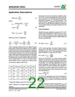
Figure 2: SE/BTL input selection by phonejack plug
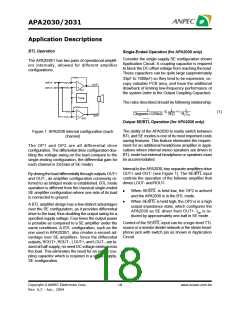
In Figure 2, input SE/BTL operates as follows:
When the phonejack plug is inserted, the 1kΩ resis-
tor is disconnected and the SE/BTL input is pulled
high and enables the SE mode. When the input goes
high level, the OUT- amplifier is shutdown causing
the speaker to mute. The OUT+ amplifier then drives
through the output capacitor (CO) into the headphone
jack.
Input Resistance, Ri
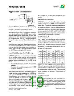
The APA2030/1 provides four gain setting decided by
GAIN0 and GAIN1 input ins in Differential mode and it
become 4.1dB fixed gain when SE mode is selected
(for APA2030). In table 1,internal resistors Ri and Rf
according to BTL operation set the gain for each au-
dio input of the APA2030/1.
When there is no headphone plugged into the system,
the contact pin of the headphone jack is connected
from the signal pin, the voltage divider set up by re-
sistors 100kΩ and 1kΩ. Resistor 1kΩ then pulls low
the SE/BTL pin, enabling the BTL function.
GAIN0
GAIN1
Ri
Rf
SE/BTL
Av
Input HP/LINE Operation (for APA2030 only)
0
0
1
1
X
0
1
0
1
X
90KΩ
69KΩ
42KΩ
90KΩ
111KΩ
138KΩ
0
0
0
0
1
6dB
10dB
15.6dB
21.6dB
4.1dB
APA2030 amplifier has two separate inputs for each of
the left and right stereo channels. An internal multi-
plexer selects which input will be connected to the
amplifier based on the state of the HP/LINE pin on
the IC.
25.7KΩ 154.3KΩ
69KΩ 111KΩ
•
To select the line inputs, set HP/LINE pin tied to
lowlevel
Table 1: The close loop gain setting resistance Ri/Rf
BTL mode operation brings about the factor 2 in the
gain equation due to the inverting amplifier mirroring
the voltage swing across the load. The input resis-
tance has wide variation (+/-10%) caused by
manufacture.
•
To enable the headphone inputs, set HP/ LINE
pin tied to high level
Refer to the application circuit, the voltage divider of
100kΩ and 1kΩ sets the voltage at the HP/LINE pin
to be approximately 50mV when there are no head-
phones plugged into the system. This logic low volt-
age at the HP/LINE pin enables the APA2030 and
places it LINE input mode operation.
Input Capacitor, Ci
In the typical application an input capacitor, Ci, is
required to allow the amplifier to bias the input signal
to the proper DC level for optimum operation. In this
case, Ci and the minimum input impedance Ri form a
high-pass filter with the corner frequency determined
in the follow equation:
When a set of headphones is plugged into the system,
the contact pin of the headphone jack is disconnected
from the signal pin, interrupting the voltage divider set
up by resistors 100kΩ. Resistor 100kΩ then pulls-up
Copyright ANPEC Electronics Corp.
19
www.anpec.com.tw
Rev. A.2 - Apr., 2004

 ANPEC [ ANPEC ELECTRONICS COROPRATION ]