the asynchronous clear sets Q LOW, regardless of the Combinatorial Feedback
clock state. If both terms are satisfied simultaneously, the
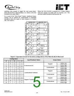
The signal-select multiplexer gives the macrocell the ability
clear will override the preset.
to feedback the output of the OR gate, bypassing the
output buffer, regardless of whether the output function is
registered or combinatorial. This feature allows the creation
of asynchronous latches, even when the output must be
disabled. (Refer to configurations 5, 6, 7, and 8 in Figure 5.)
Output Polarity
Each macrocell can be configured to implement active-high
or active-low logic. Programmable polarity eliminates the
need for external inverters.
Registered Feedback
Output Enable
Feedback also can be taken from the register, regardless
of whether the output function is programmed to be
The output of each I/O macrocell can be enabled or
disabled under the control of its associated programmable
output enable product term. When the logical conditions
programmed on the output enable term are satisfied, the
output signal is propagated to the I/O pin. Otherwise, the
output buffer is switched into the high-impedance state.
combinatorial or registered. When implementing
a
combinatorial output function, registered feedback allows
for the internal latching of states without giving up the use
of the external output.
Programmable Clock Options
Under the control of the output enable term, the I/O pin can
function as a dedicated input, a dedicated output, or a bi- A unique feature of the PEEL18LV8Z is a programmable
directional I/O. Opening every connection on the output clock multiplexer that allows the user to select true or
enable term will permanently enable the output buffer and complement forms of either input pin or product-term clock
yield a dedicated output. Conversely, if every connection is sources.
intact, the enable term will always be logically false and the
I/O will function as a dedicated input.
Operates in both 3 Volt and 3.3 Volt Systems
The PEEL18LV8Z is designed to operate with a V CC range
of 2.7 to 3.6 Volts D.C. This allows operation in both 3 Volt
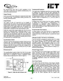
Input/Feedback Select
The PEEL18LV8Z macrocell also provides control over the 10% (battery operated) and 3.3 Volt 10% (power supply
feedback path. The input/feedback signal associated with operated) systems. The propagation delay t PD is 5 ns
each I/O macrocell can be obtained from three different slower at the lower voltage, but this is typically not an issue
locations; from the I/O input pin, from the Q output of the in battery-operated systems (see
-
A.C. Electrical
flip-flop (registered feedback), or directly from the OR gate CharacteristicsTable 1 - Absolute Maximum Ratings- A.C.
(combinatorial feedback).
Electrical Characteristics).
Bi-directional I/O
Schmitt Trigger Inputs
The PEEL18LV8Z has Schmitt trigger input buffers on all
inputs, including the clock. Schmitt trigger inputs allow
direct input of slow signals such as biomedical and sine
waves or clocks. They are also useful in cleaning up noisy
signals. This makes the PEEL18LV8Z especially desirable
in portable applications where the environment is less
predictable.
The input/feedback signal is taken from the I/O pin when
using the pin as a dedicated input or as a bi-directional I/O.
(Note that it is possible to create a registered output
function with a bi-directional I/O, refer to Figure 4).
Zero Power Feature
The CMOS PEEL18LV8Z features "Zero-Power" standby
operation for ultra-low power consumption. With the "Zero-
Power" feature, transition-detection circuitry monitors the
inputs, I/Os (including CLK) and feedbacks. If these signals
do not change for a period of time greater than
approximately three t PD 's, the outputs are latched in their
current state and the device automatically powers down.
When the next signal transition is detected, the device will
"wake up" for active operation until the signals stop
Figure 4 - PEEL18LV8Z I/O Macro cell
Anachip Corp.
www.anachip.com.tw
Rev. 1.0 Dec 16, 2004
4/10

 ANACHIP [ ANACHIP CORP ]