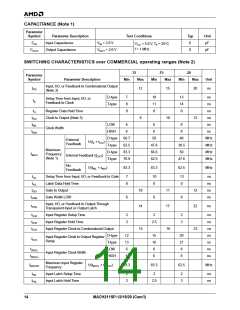
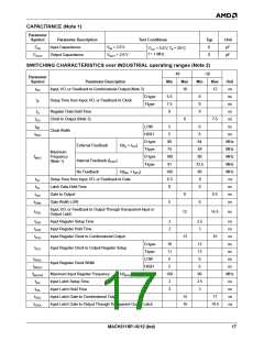
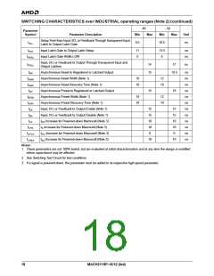
SWITCHING CHARACTERISTICS over INDUSTRIAL operating ranges (Note 2) (continued)
-10
-12
Parameter
Symbol
Parameter Description
Min
Max
Min
Max
Unit
Setup Time from Input, I/O, or Feedback Through Transparent Input
Latch to Output Latch Gate
t
8.5
10.5
ns
SLL
t
Input Latch Gate to Output Latch Setup
Input Latch Gate Width LOW
11
5
13.5
6
ns
ns
IGS
t
WIGL
Input, I/O, or Feedback to Output Through Transparent Input and
Output Latches
t
14
15
17
ns
PDLL
t
Asynchronous Reset to Registered or Latched Output
Asynchronous Reset Width (Note 1)
19.5
ns
ns
ns
ns
ns
ns
ns
ns
ns
ns
ns
ns
AR
t
10
10
12
10
ARW
t
Asynchronous Reset Recovery Time (Note 1)
Asynchronous Preset to Registered or Latched Output
Asynchronous Preset Width (Note 1)
ARR
t
15
18
AP
t
10
10
12
10
APW
t
Asynchronous Preset Recovery Time (Note 1)
Input, I/O, or Feedback to Output Enable (Note 1)
Input, I/O, or Feedback to Output Disable (Note 1)
APR
t
15
15
10
10
0
15
15
10
10
0
EA
ER
t
t
t
Increase for Powered-down Macrocell (Note 3)
LP
PD
t
t Increase for Powered-down Macrocell (Note 3)
S
LPS
t
t
t
Increase for Powered-down Macrocell (Note 3)
Increase for Powered-down Macrocell (Note 3)
LPCO
CO
EA
t
10
10
LPEA
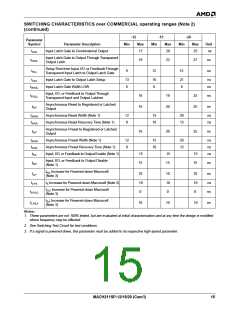
Notes:
1. These parameters are not 100% tested, but are evaluated at initial characterization and at any time the design is modified
where capacitance may be affected.
2. See Switching Test Circuit for test conditions.
3. If a signal is powered-down, this parameter must be added to its respective high-speed parameter.
18
MACH211SP-10/12 (Ind)

 AMD [ AMD ]