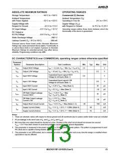
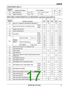
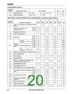
CAPACITANCE (Note 1)
Parameter
Symbol
Parameter Description
Test Conditions
= 5.0 V, T = 25°C
Typ
6
Unit
pF
C
Input Capacitance
Output Capacitance
V = 2.0 V
IN
V
IN
CC
A
f = 1 MHz
C
V
= 2.0 V
8
pF
OUT
OUT
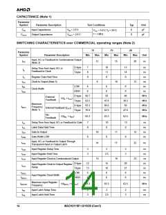
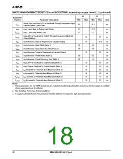
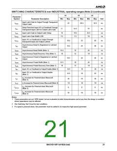
SWITCHING CHARACTERISTICS over INDUSTRIAL operating ranges (Note 2)
-10
-12
Parameter
Symbol
Parameter Description
Min
Max
Min
Max
Unit
ns
t
Input, I/O, or Feedback to Combinatorial Output (Note 3)
10
12
PD
D-type
T-type
6.5
7.5
0
8
9
0
ns
t
Setup Time from Input, I/O, or Feedback to Clock
S
H
ns
t
Register Data Hold Time
Clock to Output (Note 3)
ns
t
t
6
7.5
ns
CO
WL
WH
LOW
5
5
6
6
ns
Clock Width
t
HIGH
D-type
T-type
D-type
T-type
ns
80
74
100
91
100
6.5
0
64
59
80
72.5
80
8
MHz
MHz
MHz
MHz
MHz
ns
External Feedback
1/(t + t
)
S
CO
Maximum
Frequency
(Note 1)
f
MAX
Internal Feedback (f
No Feedback
)
CNT
1/(t + t
)
WL
WH
t
Setup Time from Input, I/O, or Feedback to Gate
Latch Data Hold Time
SL
t
0
ns
HL
t
Gate to Output
8
8.5
ns
GO
t
Gate Width LOW
5
6
ns
GWL
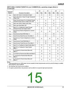
Input, I/O, or Feedback to Output Through Transparent Input or
Output Latch
t
12
14.5
ns
PDL
t
Input Register Setup Time
2
2
2.5
3
ns
ns
SIR
HIR
ICO
t
Input Register Hold Time
t
Input Register Clock to Combinatorial Output
13
16
ns
D-type
Input Register Clock to Output Register Setup
T-type
10
11
5
12
13
6
ns
t
ICS
ns
t
LOW
ns
WICL
Input Register Clock Width
HIGH
t
5
6
ns
WICH
f
Maximum Input Register Frequency
Input Latch Setup Time
1/(t
+ t )
WICH
100
2
80
2.5
3
MHz
ns
MAXIR
WICL
t
SIL
t
Input Latch Hold Time
2
ns
HIL
t
Input Latch Gate to Combinatorial Output
14
16
17
ns
IGO
t
Input Latch Gate to Output Through Transparent Output Latch
19.5
ns
IGOL
MACH211SP-10/12 (Ind)
17

 AMD [ AMD ]