Automatic pad field insertion is controlled by the
APAD_XMT bit in CSR4.
APAD_XMT is 0, which will disable automatic pad gen-
eration after H_RESET.
The disable FCS generation/transmission feature can
be programmed as a static feature or dynamically on a
frame-by-frame basis.
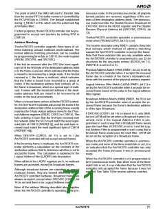
It is the responsibility of upper layer software to cor-
rectly define the actual length field contained in the
message to correspond to the total number of LLC data
bytes encapsulated in the frame (length field as defined
in the ISO 8802-3 (IEEE/ANSI 802.3) standard). The
length value contained in the message is not used by
the Am79C978 controller to compute the actual num-
ber of pad bytes to be inserted. TheAm79C978 control-
ler will append pad bytes dependent on the actual
number of bits transmitted onto the network. Once the
last data byte of the frame has completed, prior to ap-
pending the FCS, the Am79C978 controller will check
to ensure that 544 bits have been transmitted. If not,
pad bytes are added to extend the frame size to this
value, and the FCS is then added. See Figure 35.
Transmit FIFO Watermark (XMTFW) in CSR80 sets
the point at which the BMU requests more data from
the transmit buffers for the FIFO. A minimum of
XMTFW empty spaces must be available in the trans-
mit FIFO before the BMU will request the system bus in
order to transfer transmit frame data into the transmit
FIFO.
Transmit Start Point (XMTSP) in CSR80 sets the point
when the transmitter actually attempts to transmit a
frame onto the media. A minimum of XMTSP bytes
must be written to the transmit FIFO for the current
frame before transmission of the current frame will be-
gin. (When automatically padded packets are being
sent, it is conceivable that the XMTSP is not reached
when all of the data has been transferred to the FIFO.
In this case, the transmission will begin when all of the
frame data has been placed into the transmit FIFO.)
The default value of XMTSP is 01b, meaning there has
to be 64 bytes in the transmit FIFO to start a transmis-
sion.
The 544 bit count is derived from the following:
Minimum frame size (excluding preamble/SFD,
including FCS)
Preamble/SFD size 8 bytes
FCS size 4 bytes
64 bytes
512 bits
64 bits
32 bits
The 544 bit count is derived from the following:
Minimum frame size (excluding preamble/SFD,
Automatic Pad Generation
including FCS)
Preamble/SFD size 8 bytes
FCS size 4 bytes
64 bytes
512 bits
64 bits
32 bits
Transmit frames can be automatically padded to ex-
tend them to 64 data bytes (excluding preamble). This
allows the minimum frame size of 64 bytes (512 bits)
for IEEE 802.3/Ethernet to be guaranteed with no soft-
ware intervention from the host/controlling process.
Setting the APAD_XMT bit in CSR4 enables the auto-
matic padding feature. The pad is placed between the
LLC data field and FCS field in the IEEE 802.3 frame.
FCS is always added if the frame is padded, regardless
of the state of DXMTFCS (CSR15, bit 3) or ADD_FCS
(TMD1, bit 29). The transmit frame will be padded by
bytes with the value of 00h. The default value of
At the point that FCS is to be appended, the transmitted
frame should contain:
Preamble/SFD + (Min Frame Size - FCS)
64 + (512-32) = 544 bits
A minimum length transmit frame from theAm79C978
controller, therefore, will be 576 bits after the FCS is ap-
pended.
.
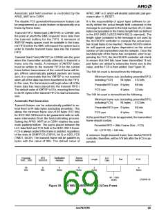
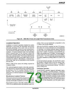
Preamble
1010....1010
SFD
10101011
Destination
Address
Source
Address
LLC
Data
Length
Pad
FCS
56
Bits
8
Bits
6
6
2
4
Bytes
Bytes
Bytes
Bytes
46 – 1500
Bytes
22206B-38
Figure 35. ISO 8802-3 (IEEE/ANSI 802.3) Data Frame
Am79C978
69

 AMD [ AMD ]