The point at which the BMU will start to transfer data
from the receive FIFO to buffer memory is controlled by
the RCVFW bits in CSR80. The default established
during H_RESET is 01b, which sets the watermark flag
at 64 bytes filled.
miscuous mode. In the promiscuous mode, all properly
formed packets are received, regardless of the con-
tents of their destination address fields. The promiscu-
ous mode overrides the Disable Receive Broadcast bit
(DRCVBC bit l4 in the MODE register) and the Disable
Receive Physical Address bit (DRCVPA, CSR15, bit
13).
For test purposes, theAm79C978 controller can be pro-
grammed to accept runt packets by setting RPA in
CSR124.
TheAm79C978 controller operates in promiscuous
mode when PROM (CSR15, bit 15) is set.
Address Matching
The receive descriptor entry RMD1 contains three bits
that indicate which method of address matching
caused the Am79C978 controller to accept the frame.
Note that these indicator bits are only available when
the Am79C978 controller is programmed to use 32-bit
structures for the descriptor entries (BCR20, bit 7-0,
SWSTYLE is set to 2 or 3).
TheAm79C978 controller supports three types of ad-
dress matching: unicast, multicast, and broadcast. The
normal address matching procedure can be modified
by programming three bits in CSR15, the mode register
(PROM, DRCVPA, and DRCVBC).
If the first bit received after the SFD (the least signifi-
cant bit of the first byte of the destination address field)
is 0, the frame is unicast, which indicates that the frame
is meant to be received by a single node. If the first bit
received is 1, the frame is multicast, which indicates
that the frame is meant to be received by a group of
nodes. If the destination address field contains all 1s,
the frame is broadcast, which is a special type of multi-
cast. Frames with the broadcast address in the desti-
nation address field are meant to be received by all
nodes on the local area network.
Physical Address Match (PAM) (RMD1, bit 22) is set by
the Am79C978 controller when it accepts the received
frame due to a match of the frame’s destination ad-
dress with the content of the physical address register.
Logical Address Filter Match (LAFM) (RMD1, bit 21) is
set by the Am79C978 controller when it accepts the re-
ceived frame based on the value in the logical address
filter register.
Broadcast Address Match (BAM) (RMD1, bit 20) is set
by the Am79C978 controller when it accepts the re-
ceived frame because the frame’s destination address
is of the type 'Broadcast.’
When a unicast frame arrives at theAm79C978 control-
ler, the Am79C978 controller will accept the frame if the
destination address field of the incoming frame exactly
matches the 6-byte station address stored in the Phys-
ical Address registers (PADR, CSR12 to CSR14). The
byte ordering is such that the first byte received from
the network (after the SFD) must match the least signif-
icant byte of CSR12 (PADR[7:0]), and the sixth byte re-
ceived must match the most significant byte of CSR14
(PADR[47:40]).
If DRCVBC (CSR15, bit 14) is cleared to 0, only BAM,
but not LAFM will be set when a Broadcast frame is re-
ceived, even if the Logical Address Filter is pro-
grammed in such a way that a Broadcast frame would
pass the hash filter. If DRCVBC is set to 1 and the Log-
ical Address Filter is programmed in such a way that a
Broadcast frame would pass the hash filter, LAFM will
be set on the reception of a Broadcast frame.
When DRCVPA (CSR15, bit 13) is set to 1,the
Am79C978 controller will not accept unicast frames.
When the Am79C978 controller operates in promiscu-
ous mode and none of the three match bits is set, it is
an indication that the Am79C978 controller has only
accepted the frame because it was in promiscuous
mode.
If the incoming frame is multicast, the Am79C978 con-
troller performs a calculation on the contents of the
destination address field to determine whether or not to
accept the frame. This calculation is explained in the
Logical Address Filter (LADRF) bits description.
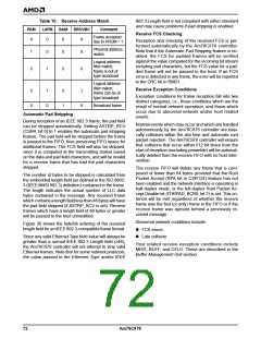
When the Am79C978 controller is not programmed to
be in promiscuous mode, then when none of the three
match bits is set, it is an indication that the Am79C978
controller only accepted the frame because it was not
rejected. See Table 10 for receive address matches.
When all bits of the LADRF registers are 0, no multicast
frames are accepted, except for broadcast frames.
Although broadcast frames are classified as special
multicast frames, they are treated differently by the
Am79C978 controller hardware. Broadcast frames are
always accepted, except when DRCVBC (CSR15, bit
14) is set and there is no Logical Address match.
None of the address filtering described above applies
when the Am79C978 controller is operating in the pro-
Am79C978
71

 AMD [ AMD ]